Page 3
120-3-20-.01 Purpose
(1) The provisions of this chapter are enacted to
further the policy of the State of Georgia to encourage and enable persons with
disabilities or elderly persons to participate fully in the social and economic
life of Georgia and to encourage and promote their education and
rehabilitation. It is the intent of this chapter to eliminate, insofar as
possible, unnecessary physical barriers encountered by persons with
disabilities or elderly persons whose ability to participate in the social and
economic life of this state is needlessly restricted when such persons cannot
readily use government buildings, public buildings, and facilities used by the
public.
(2) Unless otherwise stated in this Chapter of the
Rules and Regulations of the Georgia Safety Fire Commissioner, the following
meet the Americans With Disabilities Act Accessibility Guidelines and shall be
the minimum standard for Accessibity to buildings and facilities by individuals
with disabilities under the Americans with Disabilities Act (ADA) of 1990.
These rules are to be applied during the design, construction, and alteration
of buildings and facilities covered by Titles II and III of the ADA to the
extent required by regulations issued by Federal agencies, including the
Department of Justice and the Department of Transportation, under the ADA. The
technical specifications Rules 120-3-20-.03 through 120-3-20-.46, of these
regulations are the same as those of the American National Standard Institute's
document AU 7.1-1980, except as noted in this text by italics. However, Rules
120-3-20-.07 through 120-3-20-.12 and Rules 120-3-20-.47 through 120-3-20-.53
are different from ANSI Al 17.1 in their entirety.
The illustrations and text of ANSI Al 17.1 are
reproduced with permission from the American National Standards Institute.
Copies of the standard may be purchased from the American National Standards
Institute at 1430 Broadway, New York, New York 10018.
120-3-20-.02 Administration
(a) Except for buildings under the jurisdiction of
the Board of Regents of the University System of Georgia, all buildings subject
to the jurisdiction of the Safety Fire Commissioner pursuant to Code Section
25-2-12 and subsection (c) of Code Section 25-2-13 shall be subject to the
jurisdiction of the Safety Fire Commissioner for purposes of enforcement of
this chapter.
(b) The board of regents shall be responsible for
the administration and enforcement of this chapter with respect to all
buildings and facilities under its jurisdiction. No construction plans for any
such building or facility shall be approved by the board of regents for any
construction within the University System of Georgia unless the building or
facility conforms to O.C.G.A. 25-2-12 Rules 30-3-3 and 30-3-5 and unless the
architect or engineer responsible for preparation of said plans and
specifications affixes that person's seal on such plans. The affixing of the
seal of an architect or engineer to said plans shall constitute a certification
that to the best of that person's knowledge, information, and belief they have
been prepared in conformity with O.C.G.A. Title 30 Code Rules 30-3-3 and
30-3-5. A certificate of compliance may be displayed on said plans in lieu of
the architect's or engineer's seal. The builder, developer, contractor, or
building owner following said plans shall require an architect's or engineer's
seal or a certificate of compliance to be displayed on the plans before
starting construction.
(c) Local governing authorities shall be responsible
for the administration and enforcement of this chapter with regard to all
government and public buildings and facilities which are not under the
jurisdiction of the Safety Fire Commissioner or board of regents, pursuant to
subsections (a) and (b) of this Code section and
Page 4
which are under the jurisdiction of such local
governing authorities. No building permit for any such building or facility
shall be approved by any local governing authority for any private person,
corporation, partnership, association, or public entity unless the plans and
specifications conform to the requirements of O.C.G.A. Title 30 Code Rules
30-3-3 and 30-3-5 and unless the architect or engineer responsible for
preparation of said plans and specifications affixes that person's seal on such
plans. The affixing of the seal of an architect or engineer to said plans shall
constitute a certification that to the best of that person's knowledge,
information, and belief they have been prepared in conformity with O.C.G.A.
Title 30 Code Rules 30-3-3 and 30-3-5. A certificate of compliance may be
displayed on said plans in lieu of the architect's or engineer's seal. The
builder, developer, contractor, or building owner following said plans shall
require such a seal or a certificate of compliance on the plans before starting
construction. All construction plans must display such a certificate of
compliance, or a seal provided by the architect or engineer, for all
construction in local governing jurisdictions which do not require building
permits. In all areas where local governing authority building permits are not
required, the builder, developer, contractor, or building owner following said
plans shall require such an architect's or engineer's seal or a certificate of
compliance to be displayed on the plans before starting construction.
120-3-20-.03 Application
(1) General. All areas of newly designed or
newly constructed buildings and facilities required to be accessible by Rules
120-3-20-.07 and 120-3-20-.08 and altered portions of existing buildings and
facilities required to be accessible by Rule 120-3-20-.11 shall comply with
these Regulations, Rules 120-3-20-.03 through 120-3-20-.46, unless otherwise
provided in this section or as modified in a special application section.
(2) Application Based on Building Use. Special
application rules 120-3-20-.47 thru 120-3-20-.53 provide additional
requirements for restaurants and cafeterias, medical care facilities,
business and mercantile, libraries, accessible transient lodging,
transportation facilities and designing for Children. When a building or
facility contains more than one use covered by a special application section,
each portion shall comply with the requirements for that use.
(3) Areas Used Only by Employees as Work Areas.
Areas that are used only as work areas shall be designed and constructed so
that individuals with disabilities can approach, enter, and exit the areas.
These regulations do not require that all areas used only as work areas be
constructed to permit maneuvering within the work area or be constructed or
equipped (i.e., with racks or shelves) to be accessible.
Note: Areas Used Only by Employees
as Work Areas. Where there are a series of individual work stations of the same
type (e.g., laboratories, service counters, ticket booths),5%,
but
not
less than one, of each type of work station should be constructed
so that an individual with disabilities can maneuver within the work stations.
Rooms housing individual offices in a typical office building must meet the
requirements of the regulations concerning doors, accessible routes, etc. but
do not need to allow for maneuvering space around all individual desks.
Modifications required to permit maneuvering within
Page 5
the work area may be accomplished as a reasonable
accommodation to individual employees with disabilities under Title I of the
ADA. Consideration should also be given to placing shelves in employee work
areas at a convenient height for accessibility or installing commercially
available shelving that is adjustable so that reasonable accommodations can be
made in the future. If work stations are made accessible they should comply
with the applicable provisions of Rules 120-3-20-.03 through 120-3-20-.46.
(4) Temporary Structures. These
regulations cover temporary buildings or facilities as well as permanent
facilities. Temporary buildings and facilities are not of permanent
construction but are extensively used or are essential for public use for a
period of time. Examples of temporary buildings or facilities covered by these
regulations include, but are not limited to: reviewing
stands, temporary classrooms, bleacher areas, exhibit areas, temporary
banking facilities, temporary health screening services, or temporary safe
pedestrian passageways around a construction site. Structures,
sites and equipment directly associated with the actual processes
of construction, such as scaffolding, bridging,
materials hoists, or construction trailers are not included.
(5) General Exceptions.
(a) In new construction, a person or
entity is not required to meet fully the requirements of these regulations
where that person or entity can demonstrate that it is structurally
impracticable to do so. Full
compliance will be considered structurally impracticable only in those rare
circumstances when the unique characteristics of terrain prevent the
incorporation of accessibility features. If full compliance with the
requirements of these regulations is structurally impracticable, a person or
entity shall comply with the requirements to the extent it is not structurally
impracticable. Any portion of the building or facility which can be made
accessible shall comply to the extent that it is not structurally
impracticable.
(b) Accessibility is not
required to:
(i) observation galleries used primarily
for security purposes; or
(ii) in non-occupiable spaces accessed
only by ladders, catwalks, crawl spaces, very narrow passageways, or freight
(non-passenger) elevators, and frequented only by service personnel for repair
purposes; such spaces include, but are not limited to, elevator pits, elevator
penthouses, piping or equipment catwalks.
Page 6
120-3-20-.04 General
(1) Provisions for Adults
The specifications in these regulations are based upon
adult dimensions and anthropometries.
(2) Equivalent Facilitation
Departures from particular technical and scoping
requirements of this chapter by the use of other designs and technologies are
permitted where the alternative designs and technologies used will provide
substantially equivalent or greater access to and usability of the facility.
Note: Equivalent Facilitation. Specific
examples of equivalent facilitation are found in the following sections:
|
120-3-20-.ll(3)(c)
|
Elevators in Alterations
|
|
120-3-20-.42(9)
|
Text Telephones
|
|
120-3-49(2)
|
Sales and Service Counters, Teller Windows,
Information counters
|
|
120-3-20-.51(l)d
|
Classes of Sleeping Accommodations
|
|
120-3-20-.5I(2)(6)(d)
|
Requirements for Accessible Units, Sleeping Rooms,
and Suites
|
(3) Designing for Children.
The specifications in this standard are based upon
adult dimensions and anthropeometrics. If buildings, facilities, or portions
thereof serve children primarily, they shall comply with provisions of
120-3-20-.53.
120-3-20-.05
Miscellaneous Instructions
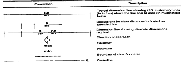
(a) Graphic Conventions. Graphic
conventions are shown in Table 1. Dimensions that are not marked minimum or
maximum are absolute, unless otherwise indicated in the text or captions.
Table 1 Graphic Conventions
Page 7
(b) Dimensional Tolerances. All
dimensions are subject to conventional building industry tolerances for field
conditions.
(c) Notes. The
text of these regulations contains additional information, and explanations.
Rules, paragraphs, and subparagraphs marked with a "Note:" This
additional information shall have the same effect as the specific requirements
and shall be considered to be additional to the minimum accessible requirement.
(d) General Terminology.
Comply with............ Must
meet one or more specifications.
if. if... then..............
Denotes
a specification that applies only when the conditions described are present.
may...............................
Denotes
an option or alternative.
shall..............................
Denotes
a mandatory specification or requirement.
should.......................
Denotes
an advisory specification or recommendation.
120-3-20-.06 Definitions
Unless a different meaning is required by the
context, the following terms as used in these rules and regulations shall have
the meaning hereinafter respectively ascribed to them. Where terms are not
defined, they shall have their ordinarily accepted meaning or such as context
applies unless defined in O.C.GA. Title 30 Chapter 3. Words used in the present
tense included the future; Words used in the masculine gender includes the
feminine and neuter; the singular includes the plural and the plural the
singular.
(a) Above Finished Floor (A.F.F.) means
the distance above the finish floor surface.
(b) Access Aisle. An
accessible pedestrian space between elements, such as parking spaces, seating,
and desks, that provides clearances appropriate for use of the elements.
(c) Accessible. Describes
a site, building, facility, or portion thereof that complies with these
regulations.
(d) Accessible Element. An
element specified by these regulations (i.e., telephone, controls).
(e) Accessible Route. A continuous
unobstructed path connecting all accessible elements and spaces of a building
or facility. Interior accessible routes may include corridors, floors, ramps,
elevators, lifts, and clear floor space at fixtures. Exterior accessible routes
may include parking access aisles, curb ramps, crosswalks at vehicular ways,
walks, ramps, and lifts.
(f) Accessible Space. Space
that complies with these regulations.
(g) Adaptability. The
ability of certain building spaces and elements, such as kitchen counters,
sinks, and grab bars, to be added or altered so as to accommodate the needs of
individuals with or without disabilities or to accommodate the needs of persons
with different types or degrees of disability.
(h) Addition. An
expansion, extension, or increase in the gross floor area of a building or
facility.
Page 8
(i) Administrative Authority. A governmental agency
that adopts or enforces regulations and regulations for the design,
construction, or alteration of buildings and facilities.
(j) Alteration. An alteration is a change to a
building or facility made by, on behalf of, or for the use of a public
accommodation or commercial facility, that affects or could affect the usability
of the building or facility or part thereof. Alterations include, but are not
limited to, remodeling, renovation, rehabilitation, reconstruction, historic
restoration, changes or rearrangement of the structural parts or elements, and
changes or rearrangement in the plan configuration of walls and full-height
partitions. Normal maintenance, re-roofing, painting or wallpapering, or
changes to mechanical and electrical systems are not alterations unless they
affect the usability of the building or facility.
(k) Area of Rescue Assistance. An area, which has
direct access to an exit, where people who are unable to use stairs may remain
temporarily in safety to await further instructions or assistance during
emergency evacuation. The area of rescue assistance space shall protected from
fire or smoke, separated from all other spaces in the same building or an
adjacent building that permits a delay in egress travel from any level.
(1) Assembly Area. A room or space accommodating a
group of individuals for recreational, educational, political, social, or
amusement purposes, or for the consumption of food and drink.
(m) Assistive. An electrical, hydraulic, or
mechanical means of increasing power.
(n) Automatic Door. A door equipped with a
power-operated mechanism and controls that open and close the door
automatically upon receipt of a momentary actuating signal. The switch that
begins the automatic cycle may be a photoelectric device, floor mat, or manual
switch
(o) Bollard. One of a series of short posts, used for
excluding motor vehicles from pedestrian way.
(p) Building. Any structure used and intended for
supporting or sheltering any use or occupancy.
(q) Circulation Path. An exterior or interior way of
passage from one place to another for pedestrians, including, but not limited
to, walks, hallways, courtyards, stairways, and stair landings.
(r) Clear. Unobstructed.
(s) Clear Floor Space. The minimum unobstructed
floor or ground space required to accommodate a single, stationary wheelchair
and occupant.
(t) Closed Circuit Telephone. A telephone with
dedicated line(s) such as a house phone, courtesy phone or phone that must be
used to gain entrance to a facility.
(u) Commissioner means the Safety Fire Commissioner
provided for in Chapter 2 of Title 25.
(v) Common Use. Refers to those interior and
exterior rooms, spaces, or elements that are made available
Page 9
for the use of a restricted group of people (for
example, occupants of a homeless shelter, the occupants of an office building,
or the guests of such occupants).
(w) Covered Multi Family Dwelling means a building
which had occupancy after March 31,1993, and consists of four or more units and
has an elevator or the ground floor units of a building which consists of four
or more units and does not have an elevator.
(x) Cross Slope. The slope that is perpendicular to
the direction of travel (see running slope), (y) Curb Ramp. A short ramp
cutting through a curb or built up to it.
(z) Detectable Warning. A standardized surface
feature built in or applied to walking surfaces or other elements to warn
visually impaired people of hazards on a circulation path.
(aa) Dwelling Unit. A single unit which provides a
kitchen or food preparation area, in addition to rooms and spaces for living,
bathing, sleeping, and the like. Dwelling units include a single family home or
a town house used as a transient group home; an apartment building used as a
shelter; guest rooms in a hotel that provide sleeping accommodations and food
preparation areas; and other similar facilities used on a transient basis. For
purposes of these regulations, use of the term "Dwelling Unit" does
not imply the unit is used as a residence.
(bb) Egress, Means of A continuous and unobstructed
way of exit travel from any point in a building or facility to a public way. A
means of egress comprises vertical and horizontal travel and may include
intervening room spaces, doorways, hallways, corridors, passageways, balconies,
ramps, stairs, enclosures, lobbies, horizontal exits, courts and yards. An accessible
means of egress is one that complies with these regulations and does not
include stairs, steps, or escalators . Area of rescue assistance or evacuation
elevators may be included as part of accessible means of egress.
(cc) Entrance. Any access point to a building or
portion of a building or facility used for the purpose of entering. An entrance
includes the approach walk, the vertical access leading to the entrance
platform, the entrance platform itself, vestibules if provided, the entry
door(s) or gate(s), and the hardware of the entry door(s) or gate(s).
(dd) Essential Features. Those elements and spaces
that make a building or facility usable by, or serve the needs of, its
occupants or users. Essential features include but are not limited to entrances,
toilet rooms, and accessible routes.
(ee) Facilities shall include, but is not limited
to, all or any portion of buildings, structures, site improvements, complexes,
equipment, roads, walks, walkways, passageways, sidewalks, curbing, parking
lots, parks, stadiums, coliseums, and any other man made or developed area used
by the public or other real or personal property located on a site.
Page 10
(ff) Government
Buildings means all buildings, structures, streets, sidewalks, walkways, and
access thereto, which are used by the public or in which persons with
disabilities or elderly persons may be employed, that are constructed, leased,
or renovated in whole or in part by use of state, county, or municipal funds or
the funds of any political subdivisions of the state, and, to the extent not
required otherwise by federal law or regulations and not beyond the power of
the state to regulate, all buildings and structures used by the public which
are constructed or renovated in whole or in part by use of federal funds.
(gg) Ground Floor. Any occupiable floor less than
one story above or below grade with direct access to grade. A building or
facility always has at least one ground floor and may have more than one ground
floor as where a split level entrance has been provided or where a building is
built into a hillside.
(hh) Infeasible means where structural conditions in
an existing building or facility make it virtually impossible to meet the
accessibility requirements for alterations, those accessibly requirements will
be deemed "technically infeasible." For example, the removal or
altering of a load-bearing member in order to provide accessibility would be
infeasible.
(ii) Mezzanine or Mezzanine Floor. That portion of a
story which is an intermediate floor level placed within the story and having
occupiable space above and below its floor.
(jj) Marked Crossing. A crosswalk or other
identified path intended for pedestrian use in crossing a vehicular way.
(kk) Multifamily Dwelling. Any building containing
more than two dwelling units.
(ll) Occupiable. A room or enclosed space designed
for human occupancy in which individuals congregate for amusement, educational
or similar purposes, or in which occupants are engaged at labor, and which is
equipped with means of egress, light, and ventilation.
(mm) Operable Part. A part of a piece of equipment
or appliance used to insert or withdraw objects, or to activate, deactivate, or
adjust the equipment or appliance (for example, coin slot, push button,
handle).
(oo) Path of Travel. Is a continuous, unobstructed
route by which the primary function area can be approached, entered, and
exited, and which connects the area with the entrance to the facility and other
parts of the facility.
(pp) Power-assisted Door. A door used for human
passage with a mechanism that helps to open the door, or relieves the opening
resistance of a door, upon the activation of a switch or a continued force
applied to the door itself.
(qq) Public Buildings means all buildings,
structures, streets, sidewalks, walkways, and access thereto, which are used by
the public or in which persons with disabilities or elderly persons may be
employed, that are constructed or renovated by the use of private funds,
including rental apartment complexes of twenty or more units or more and
temporary lodging facilities of 20 units or more, but excluding covered
multifamily
Page 11
dwellings; provided, however, that this chapter
shall require fully accessible adaptable units in only 2 percent of the total
rental apartments, or a minimum of one, whichever is greater, and this chapter
shall apply to only 5 percent of the total temporary lodging units, or a
minimum of one, whichever is greater; provided, further that this chapter shall
not apply to a private single-family residence or to duplexes or any complex
containing less than 20 units, or residential condominiums. Fifty percent of
the fully accessible or adaptable rental apartment units required by this
paragraph shall be adaptable for a roll in shower stall.
(rr) Public Use. Describes interior or exterior
rooms or spaces that are made available to the general public. Public use may
be provided at a building or facility that is privately or publicly owned.
(ss) Ramp. A walking surface which has a running
slope greater than 1:20.
(tt) Reasonable Number for all government buildings,
public buildings, and facilities receiving permits for construction or
renovation after July 1,1995, as used in Code Section 30-3-4, shall meet the
number as established by ADAAG.
(uu) Renovation means:
(a) if any specific component of an elevator is
replaced or moved from its existing location to a different location, then the
specific component shall be required to meet the ANSI A117.1 standard, as
specified in this Code Section, as it applies to that specific component,
including an accessible route as defined in the ANSI Al17.1 Standard;
(b) Any component of a building, structure, or
facility, which is replaced, except for the purpose of repair, or moved, shall
be required to meet the ANSI A117.1 Standard as specified in this Code Section,
including an accessible route as defined in the ANSI Al 17.1 Standard; or
(c) The resurfacing, rest ripping, or repainting of
any parking facility, wether or not such resurfacing, rest ripping, repainting
is required to have a permit from the appropriate political subdivision.
(w) Running Slope. The slope that is parallel to the
direction of travel (see cross slope).
(rr) Service Entrance. An entrance intended
primarily for delivery of goods or services, (ss) Signage. Displayed verbal,
symbolic, tactile, and pictorial information.
(tt) Site. A parcel of land bounded by a property
line or a designated portion of a public right-of-way.
(uu) Site Improvement. Landscaping, paving for
pedestrian and vehicular ways, outdoor lighting, recreational facilities, and
the like, added to a site.
(w) Sleeping Accommodations. Rooms in which people
sleep; for example, dormitory and hotel or motel guest rooms or suites.
Page 12
(ww) Space. A definable area, e.g., room, toilet
room, hall, assembly area, entrance, storage room, alcove, courtyard, or lobby.
(xx) Story. That portion of a
building included between the upper surface of a floor and upper surface of the
floor or roof next above. If such portion of a building does not include
occupiable space, it is not considered a story for purposes of these
regulations. There may be more than one floor level within a story as in the
case of a mezzanine or mezzanines.
(yy) Structural Frame. The structural frame shall be
considered to be the columns and the girders, beams, trusses and spandrels
having direct connections to the columns and all other members which are
essential to the stability of the building as a whole.
(zz) Structural impracticability means only in those
rare circumstances when the unique characteristics of terrain prevent the
incorporation of accessibility features. Changes having little likelihood of
being accomplished without removing or altering a load-bearing structural
member and/or incurring an increase cost of 50 percent or more of the value of
the element of the building or facility involved.
(aaa)Tactile. Describes an object that can be
perceived using the sense of touch.
(bbb)Tactile Warning. A standardized surface texture
applied to or built into walking surfaces or other elements to warn visually
impaired people of hazards in the path of travel.
(ccc ) Technically Infeasible. Means, with respect
to an alteration of a building or facility, that it has little likelihood of
being accomplished because of existing structural conditions would require
removing or altering a load bearing member which is an essential part of the
structural frame; or because other existing physical or site constraints
prohibit modification or addition of elements, spaces, or features which are in
full and strict compliance with the minimum requirements for new construction
and which are necessary to provide accessibility.
(ddd) Text Telephone. Machinery or equipment that
employs interactive graphic (i.e., typed) communications through the
transmission of coded signals across the standard telephone network. Text
telephones can include, for example, devices known as TDD's (telecommunication
display devices or telecommunication devices for deaf persons) or computers.
(eee) Transient Lodging. A building, facility, or
portion thereof, excluding inpatient medical care facilities, that contains one
or more dwelling units or sleeping accommodations. Transient lodging may
include, but is not limited to, resorts, group homes, hotels, motels, and
dormitories.
(fff) Vehicular Way. A route intended for vehicular
traffic, such as a street, driveway, or parking lot.
(ggg) Walk. An exterior pathway with a prepared
surface intended for pedestrian use, including general pedestrian areas such as
plazas and courts.
Page 13
120-3-20-.07 Accessible Sites
and Exterior Facilities: New Construction
An accessible site shall meet the following minimum
requirements:
(a) At least one accessible route complying with
Rule 120-3-20-.14 shall be provided within the boundary of the site from public
transportation stops, accessible parking spaces, passenger loading zones if
provided, and public streets or sidewalks, to an accessible building entrance.
(b) At least one accessible route complying with
rule 120-3-20-.14 shall connect accessible buildings, accessible facilities,
accessible elements, and accessible spaces that are on the same site.
(c) All objects that protrude from surfaces or posts
into circulation paths shall comply with rule 120-3-20-.15
(d) Ground surfaces along accessible routes and in
accessible spaces shall comply with rule 120-3-20-.16.
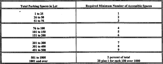
(e) 1. If parking spaces are provided for
self-parking by employees or visitors, or both, then accessible spaces
complying with rule 120-3-20-.17 shall be provided in each such parking area in
conformance with the table below. Spaces required by the table need not be
provided in the particular lot. They may be provided in a different location if
equivalent or greater accessibility, in terms of distance from an accessible
entrance, cost and convenience is ensured.
Except as provided in (b), access aisles adjacent to
accessible spaces shall be 60 inches (1525 mm) wide minimum.
2. One in every eight accessible spaces, but not
less than one, shall be served by an access aisle 96 inches (2440 mm) wide
minimum and shall be designated "van accessible" as required by rule
120-3-20-.17(4). The vertical clearance at such spaces shall comply with rule
120-3-20-.17(5). All such spaces may be grouped on one level of a parking
structure.
EXCEPTION: Provision of all required parking spaces
in conformance with "Universal Parking Design" (fig. A5)
3. If passenger loading zones are provided, then at
least one passenger loading zone shall comply with rule 120-3-20-.17(6).
4. At facilities providing medical care and
facilities providing other services for persons with mobility
Page 14
impairments, parking spaces complying with
rulel20-3-20-.17 shall be provided in accordance with rule 120-3-20-.07(5)(a)
except as follows:
Exception 1: Outpatient units and facilities:
10 percent of the total number of parking spaces provided serving each such
outpatient unit or facility;
Exception 2: Units and facilities that
specialize in treatment or services for persons with mobility impairments: 20
percent of the total number of parking spaces provided serving each such unit
or facility.
5. Valet parking: Valet parking facilities shall
provide a passenger loading zone complying with rule 120-3-20-.17(6) located on
an accessible route to the entrance of the facility. Paragraphs 5(a), 5(b), and
5(d) of this section do not apply to valet parking facilities.
Notes: Valet parking is not
always usable by individuals with disabilities. For instance, an individual may
use a type of vehicle controls that render the regular controls inoperable or
the driver's seat in a van may be removed. In these situations, another person
cannot park the vehicle. It is recommended that some self-parking spaces be provided
at valet parking facilities for individuals whose vehicles cannot be parked by
another person and that such spaces be located on an accessible route to the
entrance of the facility.
6. If toilet facilities are provided on a site, then
each such public or common use toilet facility shall comply with 120-3-20-.33.
If bathing facilities are provided on a site, then each such public or common
use bathing facility shall comply with 120-3-20-.34. For single user portable
toilet or bathing units clustered at a single location, at least 5% but no less
than one toilet unit or bathing unit complying with 120-3-20-.33 or
120-3-20-.34 shall be installed at each cluster whenever typical inaccessible
units are provided. Accessible units shall be identified by the International
Symbol of Accessibility.
EXCEPTION: Portable toilet units at
construction sites used exclusively by construction personnel are not required
to comply with 120-3-20-07(6).
7. Building Signage. Signs which designate permanent
rooms and spaces shall comply with rules 120-3-20-.41(l), 120-3-20-.41(4),
120-3-20-.41(5) and 120-3-20-.41(6). Other signs which provide direction to, or
information about, functional spaces of the building shall comply with rules
120-3-20-.41(1), 120-3-20-.41(2), 120-3-20-.41(3), and 120-3-20-.41(5).
Elements and spaces of accessible facilities which shall be identified by the
International Symbol of Accessibility and which shall comply with rule
120-3-20-.41(7) are:
(i) Parking spaces designated
as reserved for individuals with disabilities;
(ii) Accessible
passenger loading zones;
(iii) Accessible
entrances when not all are accessible (inaccessible
entrances shall have directional signage to indicate the route to the nearest
accessible entrance);
(iiii) Accessible
toilet and bathing facilities when not all are accessible.
Page 15
120-3-20-.08 Accessible
Buildings: New Construction
Accessible buildings and facilities shall meet the
following minimum requirements:
(1) At least one
accessible route complying with rule 120-3-20-.14 shall connect accessible
building or facility entrances with all accessible spaces and elements within
the building or facility.
(2) All objects that
overhang or protrude into circulation paths shall comply with rule
120-3-20-.15.
(3) Ground and floor
surfaces along accessible routes and in accessible rooms and spaces shall
comply with rule 120-3-20-.16.
(4) Interior and
exterior stairs connecting levels that are not connected by an elevator, ramp,
or other accessible means of vertical access shall comply with rule
120-3-20-.20.
(5) One passenger elevator
complying with rule 120-3-20-.21 shall serve each level, including mezzanines,
in all multi-story buildings and facilities unless exempted below. If more than
one elevator is provided, each full passenger elevator shall comply with rule
120-3-20-.21.
EXCEPTION 1: Elevators are not required in
facilities that are less than three stories or that have less than 3000 square
feet per story unless the building is a shopping center, a shopping mall, or
the professional office of a health care provider, or another type of facility
as determined by the U.S. Attorney General. The elevator exemption set forth in
this paragraph does not obviate or limit in any way the obligation to comply
with the other accessibility requirements established in rule 120-3-20-.08. For
example, floors above or below the accessible ground floor must meet the
requirements of this section except for elevator service. If toilet or bathing
facilities are provided on a level not served by an elevator, then toilet or
bathing facilities must be provided on the accessible ground floor. In new
construction if a building or facility is eligible for this exemption but a
full passenger elevator is nonetheless planned, that elevator shall meet the
requirements of rule 120-3-20-.21 and shall serve each level in the building. A
full passenger elevator that provides service from a garage to only one level
of a building or facility is not required to serve other levels.
EXCEPTION 2: Elevator
pits, elevator penthouses, mechanical rooms, piping or equipment catwalks are
exempted from this requirement.
EXCEPTION 3: Accessible
ramps complying with rule 120-3-20-.19 may be used in lieu of an elevator.
EXCEPTION 4: Platform
lifts (wheelchair lifts) complying with rule 120-3-20-.22 of this regulation
and applicable state or local codes may be used in lieu of an elevator only
under the following conditions:
(a) To provide an accessible route to a performing
area in an assembly occupancy.
(b) To comply with
the wheelchair viewing position line-of-sight and dispersion requirements of
rule 120-3-20-.44(3).
(c) To provide access to incidental occupiable
spaces and rooms which are not open to the general public and which house no
more than five persons, including but not limited to equipment control rooms
and projection booths.
Page 16
(d) To provide access where existing site
constraints or other constraints make use of a ramp or an elevator infeasible.
Note: Only full passenger
elevators are covered by the accessibility provisions of rule 120-3-20-.21.
Materials and equipment hoists, freight elevators not intended for passenger
use, dumbwaiters, and construction elevators are not covered by these rules. If
a building is exempt from the elevator requirement, it is not necessary to
provide a platform lift or other means of vertical access in lieu of an
elevator.
Under Exception 4, platform
lifts are allowed where existing conditions make it
impractical to install a ramp or elevator. Such conditions generally occur
where it is essential to provide access to small raised or lowered areas where
space may not be available for a ramp. Examples include, but are not limited
to, raised pharmacy platforms, commercial offices raised above a sales floor,
or radio and news booths.
(6) Windows: (Reserved).
(7) Doors:
(a) At each accessible entrance to a building or
facility, at least one door shall comply with rule 120-3-20-.24.
(b) Within a building or facility, at least one door
at each accessible space shall comply with rule 120-3-20-.24.
(c) Each door that is an element of an accessible
route shall comply with rule 120-3-20-.24.
(d) Each door required by rule 120-3-20-.14(10),
Egress, shall comply with 1 rule 20-3-20-.24.
(8) In new construction, at a minimum, the requirements
in (a) and (b) below shall be satisfied independently:
(a) 1. All primary entrances (excluding those in
(b) below) must be accessible. At least one must be a ground floor entrance.
Public entrances are any entrances that are not loading or service entrances.
2. Accessible entrances must be provided in a number
at least equivalent to the number of exits required by the applicable
building/fire codes. (This paragraph does not require an increase in the total
number of entrances planned for a facility.)
3. An accessible entrance must be provided to each
tenancy in a facility (for example, individual stores in a strip shopping
center). One entrance may be considered as meeting more than one of the
requirements in (a). Where feasible, accessible entrances shall be the
entrances used by the majority of people visiting or working in the building.
Page 17
(b) 1. In addition,
if direct access is provided for pedestrians from an enclosed parking garage to
the building, at least one direct entrance from the garage to the building must
be accessible.
2. If access is provided for pedestrians from a
pedestrian tunnel or elevated walkway, one entrance to the building from each
tunnel or walkway must be accessible. One entrance may be considered as meeting
more than one of the requirements in (b). Because entrances also serve as
emergency exits whose proximity to all parts of buildings and facilities is
essential, it is preferable that all entrances be accessible.
(c) If the only entrance to a building, or tenancy
in a facility, is a service entrance, that entrance shall be accessible.
(d) Entrances which
are not accessible shall have directional signage complying with rules
120-3-20-.41(1), 120-3-20-.41(2), 120-3-20-.41(3), and 120-3-20-.41(5), which
indicates the location of the nearest accessible entrance.
(9) In buildings or facilities, or portions of
buildings or facilities, required to be accessible, accessible means of
egress shall be provided in the same number as required for exits by
local building/life safety regulations. Where a required exit from an
occupiable level above or below a level of accessible exit discharge is not
accessible, an area of rescue assistance shall be provided on
each such level (in a number equal to that of inaccessible required exits).
Areas of rescue assistance shall comply with rule 120-3-20-.14(11). A
horizontal exit, meeting the requirements of local building/life safety
regulations, shall satisfy the requirement for an area of rescue assistance.
EXCEPTION: Areas of rescue assistance
are not required in buildings or facilities having a supervised automatic
sprinkler system.
Note: Supervised automatic
sprinkler systems have built in signals for monitoring features of the system
such as the opening and closing of water control valves, the power supplies for
needed pumps, water tank levels, and for indicating conditions that will impair
the satisfactory operation of the sprinkler system. Because of these monitoring
features, supervised automatic sprinkler systems have a high level of
satisfactory performance and response to fire conditions.
(10) Drinking Fountains:
(a) Where only one
drinking fountain is provided on a floor there shall be a drinking fountain
which is accessible to individuals who use wheelchairs in accordance with rule
120-3-20-.26 and one accessible to those who have difficulty bending or
stooping. (This can be accommodated by the use of a "hi-lo" fountain;
by providing one fountain accessible to those who use wheelchairs and one
Page 18
fountain at a standard height convenient for those
who have difficulty bending; by providing a fountain accessible under rule
120-3-20-.26 and a water cooler; or by such other means as would achieve the
required accessibility for each group on each floor.)
(b) Where more than one drinking fountain or water
cooler is provided on a floor, 50% of those provided shall comply with rule
120-3-20-.26 and shall be on an accessible route.
Notes: If
an odd number of drinking fountains is provided on a floor, the requirement in rule
120-3-20-.08(10)(b) may be met by rounding down the odd number to an even
number and calculating 50% of the even number. When more than one drinking
fountain on a floor is required to comply with rule 120-3-20-26, those
fountains should be dispersed to allow wheelchair users convenient access. For
example, in a large facility such as a convention center that has water
fountains at several locations on a floor, the accessible water fountains
should be located so that wheelchair users do not have to travel a greater
distance than other people to use a drinking fountain.
(11) Toilet Facilities: If toilet rooms are
provided, then each public and common use toilet room shall comply with rule
120-3-20-.33. Other toilet rooms provided for the use of occupants of specific
spaces (i.e., a private toilet room for the occupant of a private office) shall
be adaptable. If bathing rooms are provided, then each public and common use
bathroom shall comply with rule 120-3-20-.34. Accessible toilet rooms and
bathing facilities shall be on an accessible route.
(12) Storage, Shelving and Display Units:
(a) If fixed or built-in storage facilities such as
cabinets, shelves, closets, and drawers are provided in accessible spaces, at
least one of each type provided shall contain storage space complying with rule
120-3-20-.36. Additional storage may be provided outside of the dimensions
required by rule 120-3-20-.36.
(b) Shelves or display units allowing self-service
by customers in mercantile occupancies shall be located on an accessible route
complying with rule 120-3-20-.14. Requirements for accessible reach range do
not apply.
(13) Controls and operating mechanisms in accessible
spaces, along accessible routes, or as parts of accessible elements (for
example, light switches and dispenser controls) shall comply with rule 120-3-20-.38.
(14) If emergency warning systems are provided, then
they shall include both audible alarms and visual alarms complying with
rule 120-3-20-.39.
Sleeping
accommodations required to comply with rule 120-3-20-.51(3) shall
have an alarm system complying with rule 120-3-20-.39. Emergency warning
systems in medical care facilities may be modified to suit standard health care
alarm design practice.
(15) Detectable warnings shall be provided at
locations as specified in rule 120-3-20-.40.
Page 19
(16) Building Signage:
(a) Signs which designate permanent rooms and spaces
shall comply with rules 120-3-20-.41 (1), 120-3-20-.41(4), 120-3-20-.41(5)and
120-3-20-.41(6).
(b) Other signs which provide direction to or
information about functional spaces of the buildina shall comply with rules
120-3-20-.41(l), 120-3-20-.41(2), 120-3-20-.41(3), and 120-3-20-.41(5).
EXCEPTION: Transitory building
directories, menus, and all other signs which are temporary in nature are not
required to comply.
(17) Public telephones:
(a) If public pay telephones, public closed circuit
telephones, or other public telephones are provided, then they shall comply
with rules 120-3-20-.42(2) through 120-3-20-.42(8) to the extent required by
the following table:
|
Number of each type of telephone provided on each
floor
|
Number of telephones required to comply with rules
120-3-20-.42 .2
through
120-3-20-.42 .
81
|
|
1 or
more single unit
|
1 per
floor
|
|
1 bank2
|
1 per
floor
|
|
2 or
more banks:
|
1 per
bank. Accessible unit may be installed as a single unit in proximity
(either visible or with signage) to the bank. At least one public
telephone per floor shall meet the requirements for a forward reach telephone3.
|
1
Additional public telephones may be installed at any height. Unless otherwise
specified, accessible telephones may be either forward or side reach
telephones.
2 A bank consists of two or more adjacent public
telephones, often installed as a unit.
3 EXCEPTION: For
exterior installations only, if dial tone first service is available, then a
side reach telephone may be installed instead of the required forward reach
telephone (i.e., one telephone in proximity to each bank shall comply with rule
120-3-20-.42).
(b) All telephones required to be accessible and
complying with rules 120-3-20-.42(2) through 120-3-20-.42(8) shall be equipped
with a volume control. In addition. 25 percent, but never less than one, of all
other public telephones provided shall be equipped with a volume control and
shall be dispersed among all types of public telephones, including closed
circuit telephones, throughout the building or facility. Signage complying with
applicable provisions of rule 120-3-20-.41 (7) shall be provided.
Page 20
(c) The following
shall be provided in accordance with rule 120-3-20-.42(9):
1. if a total
number of four or more public pay telephones (including both interior and
exterior phones) is provided at a site, and at least one is in an interior
location, then at least one interior public text telephone shall be provided.
2. if an interior
public pay telephone is provided in a stadium or arena, in a convention center,
in a hotel with a convention center, or in a covered mall, at least one
interior public text telephone shall be provided in the facility.
3. if a public pay
telephone is located in or adjacent to a hospital emergency room, hospital
recovery room, or hospital waiting room, one public text telephone shall be
provided at each such location.
(d) Where a bank of
telephones in the interior of a building consists of three or more public pay
telephones, at least one public pay telephone in each such bank shall be
equipped with a shelf and outlet in compliance with rule 120-3-20-.42(9)(b).
Notes: In addition to the requirements of
rule 120-3-20-. 08 (17) (b) , the installation of additional volume controls
is required. Volume controls can be installed on any telephone.
(18) If fixed or
built-in seating or tables (including, but not limited to, study carrels and
student laboratory stations), are provided in accessible public or common use
areas, at least five percent (5%\ but
not less than one, of the fixed or built-in
seating areas or tables shall comply with rule 120-3-20-.43. An accessible
route shall lead to and through such fixed or built-in seating areas, or
tables.
(19) * Assembly areas:
(a) In places of
assembly with fixed seating, accessible wheelchair locations shall comply with
rules 120-3 -20-.44(2), 120-3-20-.44(3), and 120-3-20-.44(4) and shall be
provided consistent with the following table:
|
Capacity of Seating in Assembly Areas
|
Number of Required Wheelchair
Locations
|
|
4 to 25
|
1
|
|
26 to 50
|
2
|
|
51 to 300
|
4
|
|
301 to 500
|
6
|
|
over 500
|
6, plus 1 additional space for each
total seating capacity increase
of 100
|
In addition, one percent, hut not less
than one, of all fixed seats shall be aisle seats with no armrests
on the aisle side, or removable or folding armrests on the aisle side. Each
such seat shall be identified by a sign or marker. Signage notifying patrons of
the availability of such seats shall be posted at the ticket office. Aisle
seats are not required to comply with rule 120-3-20-.44(4).
Page 21
Note: Readily removable or folding
seating units may be installed in lieu of providing an open space for
wheelchair users. Folding seating units are usually two fixed seats that can be
easily folded into a fixed center bar to allow for one or two open spaces for
wheelchair users when necessary. These units are more easily adapted than
removable seats which generally require the seat to be removed in advance by
the facility management. Either a sign or a marker placed on seating with
removable or folding arm rests is required by this section. Consideration
should be given for ensuring identification of such seats in a darkened theater.
For example, a marker which contrasts (light on dark or dark on light) and
which also reflects light could be placed on the side of such seating so as to
be visible in a lighted auditorium and also to reflect light from a flashlight.
(b) This paragraph
applies to assembly areas where audible communications are integral to
the use of the space (e.g., concert and lecture halls, playhouses and movie
theaters, meeting rooms, etc.). Such assembly areas, if (1) they accommodate
at least 50 persons, or if they have audio - amplification systems, and (2)
they have fixed seating, shall have a permanently installed Assistive listening
system complying with rule 120-3-20-.34. For other assembly areas, a
permanently installed assistive listening system, or an adequate number of
electrical outlets or other supplementary wiring necessary to support a
portable assistive listening system shall be provided. The minimum number of
receivers to be provided shall be equal to 4 percent of the total number of
seats, but in no case less than two. Signage complying with applicable
provisions of rule 120-3-20-.41 shall be installed to notify patrons of the
availability of a listening system.
(20) Where automated teller machines (ATMs) are
provided, each ATM shall comply with the requirements of rule 120-3-20-.45
except where two or more are provided at a location, then only one must comply.
EXCEPTION: Drive-up-only automated
teller machines are not required to comply with rules
120-3-20-.38(2), 120-3-20-.38(3) and 120-3-20--.45(3).
(21) Where dressing and fitting rooms are provided
for use by the general public, patients, customers or employees, 5% ,
but never less than one, of dressing rooms for each type of use in each cluster
of dressing rooms shall be accessible and shall comply with rule 120-3-20-.46.
Examples of types of dressing rooms are those
serving different sexes or distinct and different functions as in different
treatment or examination facilities.
120-3-20-.09 (Reserved)
120-3-20-.10 Accessible
Buildings: Additions
Each addition to an existing building or facility
shall be regarded as an alteration. Each space or element added to the existing
building or facility shall comply with the applicable provisions of rule
120-3-20-.07 to 120-3-20-.08, Minimum Requirements (for New Construction) and
the applicable technical specifications of rules 120-3-20-.13 through
120-3-20-.46 and 120-3-20-.47 through 120-3-20-.53. Each addition that affects
or could affect the usability of an area containing a primary function shall
comply with rule 120-3-20-.011.
Page 22
120-3-20-.11 Accessible
Buildings: Alterations
(1) General. Alterations to existing
buildings and facilities shall comply with the following:
(a) No alteration
shall be undertaken which decreases or has the effect of decreasing
accessibility or usability of a building or facility below the
requirements for new construction at the time of alteration.
(b) If existing
elements, spaces, or common areas are altered, then each such altered element,
space, feature, or area shall comply with the applicable provisions of rules
120-3-20-.03 to 120-3-20-.08 Minimum Requirements (for New Construction). If
the applicable provision for new construction requires that an element, space,
or common area be on an accessible route, the altered element, space, or common
area is not required to be on an accessible route except as provided in rule
120-3-20-.011 (2) (Alterations to an Area Containing a Primary
Function.)
(c) If alterations
of single elements, when considered together, amount to an alteration of a room
or space in a building or facility, the entire space shall be made
accessible.
(d) No alteration of
an existing element, space, or area of a building or facility shall
impose a requirement for greater accessibility than that which would be
required for new construction. For example, if the elevators and stairs in a
building are being altered and the elevators are, in turn, being made
accessible, then no accessibility modifications are required to the stairs
connecting levels connected by the elevator. If stair modifications to correct
unsafe conditions are required by other codes, the modifications shall be done
in compliance with these regulations unless technically infeasible.
(e) At least one
interior public text telephone complying with rule 120-3-20-.42 shall be
provided if:
(i) alterations to
existing buildings or facilities with less than four exterior or interior
public pay telephones would increase the total number to four or more
telephones with at least one in an interior location; or
(ii) Alterations to
one or more exterior or interior public pay telephones occur in an existing
building or facility with four or more public telephones with at least one in
an interior location.
(f) If an escalator
or stair is planned or installed where none existed previously and major
structural modifications are necessary for such installation, then a means
of accessible vertical access shall be provided that complies with the
applicable provisions of rules 120-3-20-.19,120-3-20-.20,120-3-20-.10,
or
120-3-20-.1l.
(g) In alterations,
the requirements of rules 120-3-20-.08 (9), 120-3-20-.14(10) and 120-3-20-.14(l
1) do not apply.
(h) Entrances: If
a planned alteration entails alterations to an entrance, and the
building has an accessible entrance, the entrance being altered is not required
to comply with 120-3-20-.08(8), except to the extent required by rule
120-3-20-.11(2). If a particular entrance is not made accessible,
appropriate accessible signage indicating the location of the nearest
accessible entrance(s) shall be installed at or near the inaccessible entrance,
such that a person with disabilities will not be required to retrace the
approach route from the inaccessible entrance.
Note: When an
entrance is being altered, it is required that those entrances being altered be
made accessible to the extent feasible.
Page 23
(i) If the
alteration work is limited solely to the electrical, mechanical, or plumbing
system, or to hazardous material abatement, or automatic sprinkler
retro-fitting, and does not involve the alteration of any elements or spaces
required to be accessible under these regulations, then rule 120-3-20-.11(2)
does not apply.
(j) EXCEPTION: In
alteration work, if compliance with rule 120-3-20-.1l
is technically infeasible, the alteration shall provide accessibility to the
maximum extent feasible. Any elements or features of the building or facility
that are being altered and can be made accessible shall be made accessible
within the scope of the alteration.
(k) EXCEPTION:
(1) These Regulations do not require the
installation of an elevator in an altered facility that is less than three
stories or has less than 3,000 square feet per story unless the building is a
shopping center, a shopping mall, the professional office of a health care
provider, or another type of facility as determined by the U.S. Attorney
General.
(ii) This exemption does
not obviate or limit in any way the obligation to comply
with the other accessibility requirements established in these regulations. For
example, alterations to floors above or below the ground floor must be
accessible regardless of whether the altered facility has an elevator. If a
facility subject to the elevator exemption set forth in paragraph (1)
nonetheless has a full passenger elevator, that elevator shall meet, to the
maximum extent feasible, the accessibility requirements of these rules.
(2) Alterations
to an Area Containing a Primary Function: In addition to the requirements of
rule 120-3-20-.11(1), an alteration that affects or could affect the usability
of or access to an area containing a primary function shall be made so as to
ensure that, to the maximum extent feasible, the path of travel to the altered area
and the rest rooms, telephones, and drinking fountains serving the altered
area, are readily accessible to and usable by individuals with disabilities,
unless such alterations are disproportionate to the overall alterations in
terms of cost and scope (as determined under criteria established by the U.S.
Attorney general).
(3) Special Technical Provisions for Alterations to
Existing Buildings and Facilities:
(a) Ramps: Curb
ramps and interior or exterior ramps to be constructed on sites or in existing
buildings or facilities where space limitations prohibit the use of a 1:12
slope or less may have slopes and rises as follows:
(i) A slope between
1:10 and 1:12 is allowed for a maximum rise of 6 inches.
(ii) A slope between
1:8 and 1:10 is allowed for a maximum rise of 3 inches. A slope steeper than
1:8 is not allowed.
(b) Stairs: Full
extension of handrails at stairs shall not be required in alterations where
such extensions would be hazardous or impossible due to plan configuration.
(c) Elevators:
(i) If
safety door edges are provided in existing automatic elevators, automatic door
reopening devices may be omitted (see rule 120-3-20-.21).
Page 24
(ii) Where existing
shaft configuration or technical in feasibility prohibits strict compliance
with rule 120-3-20-.21(9), the minimum car plan dimensions may be reduced by
the minimum amount necessary, but in no case shall the inside car area be
smaller than 48 inches by 48 inches.
(iii) Equivalent
facilitation may be provided with an elevator car of different dimensions when
usability can be demonstrated and when all other elements required to be
accessible comply with the applicable provisions of rule 120-3-20-.21. For
example, an elevator of 47 inches by 69 inches (1195 mm by 1755 mm) with a door
opening on the narrow dimension, could accommodate the standard wheelchair
clearances shown in Figure 4.
(d) Doors:
(i) Where it is
technically infeasible to comply with clear opening width requirements of rule
120-3-20-.24(5), a projection of 5/8 inch maximum will be permitted for the
latch side stop.
(ii) If existing
thresholds are 3/4 inch high or less, and have (or are modified to have) a
beveled edge on each side, they may remain.
(e) Toilet Rooms:
(i) Where it is
technically infeasible to comply with rules 120-3-20-.33 or 120-3-20-.34, the
installation of at least one unisex toilet/bathroom per floor, located in the
same area as existing toilet facilities, will be permitted in lieu of modifying
existing toilet facilities to be accessible. Each unisex toilet room shall
contain one water closet complying with rule 120-3-20-.27 and one lavatory
complying with rule 120-3-20-.30, and the door shall have a privacy latch.
(ii) Where it is
technically infeasible to install a required standard stall (Fig. 30(a)), or
where other codes prohibit reduction of the fixture count (i.e., removal of a
water closet in order to create a double-wide stall), either alternate stall
(Fig.30(b)) may be provided in lieu of the standard stall.
(iii) When existing
toilet or bathing facilities are being altered and are not made accessible,
signage complying with rules 120-3-20-.41(l), 120-3-20-.41(2), 120-3-20-.41(3),
120-3-20-.41(5)and 120-3-20-.41 (7) shall be provided indicating the location
of the nearest accessible toilet or bathing facility within the facility.
(f) Assembly Areas:
(i) Where it is
technically infeasible to disperse accessible seating throughout an altered
assembly area, accessible seating areas may be clustered. Each accessible
seating area shall have provisions for companion seating and shall be located
on an accessible route that also serves as a means of emergency egress.
(ii) Where it is
technically infeasible to alter all performing areas to be on an accessible
route, at least one of each type of performing area shall be made accessible.
(g) Platform Lifts (Wheelchair Lifts): In
alterations, platform lifts (wheelchair lifts) complying with rule 120-3-20-.22
and applicable state or local codes may be used as part of an accessible route.
The use of lifts is not limited to the four conditions in exception 4 of rule
120-3-20-.08(5).
Page 25
(h) Dressing Rooms: In alterations where technical
in feasibility can be demonstrated, one dressing room for each sex on each
level shall be made accessible. Where only unisex dressing rooms are provided,
accessible unisex dressing rooms may be used to fulfill this requirement.
120-3-20-.12 Accessible
Buildings: Historic Preservation
(1) Applicability:
(a) GeneraI Rule.
Alterations to a qualified historic building or facility shall comply with rule
120-3-20-. 11 Accessible Buildings: Alterations, the applicable technical
specifications of rules 120-3-20-.13 through 120-3-20-.46 and the applicable
special application Rules 120-3-20-.47 through 120-3-20-.52 unless it is determined
in accordance with the procedures in rule 120-3-20-.12(2) that compliance with
the requirements for accessible routes (exterior and interior), ramps,
entrances, or toilets would threaten or destroy the historic significance of
the building or facility in which case the alternative requirements in rule
120-3-20-. 12(3) may be used for the feature.
EXCEPTION: (Reserved).
(b) A qualified historic building or facility is a
building or facility that is:
(i) Listed in or
eligible for listing in the National Register of Historic Places; or
(ii) Designated as
historic under an appropriate State or local law.
(2) Procedures:
(a) Alterations to
Qualified Historic Buildings and Facilities Subject to Section 106
of the National Historic Preservation Act:
(i) Section 106 Process.
Section 106 of the National Historic Preservation Act (16 U.S.C. 470 f)
requires that a Federal agency with jurisdiction over a Federal, federally
assisted, or federally licensed undertaking consider the effects of the
agency's undertaking on buildings and facilities listed in or eligible for
listing in the National Register of Historic Places and give the Advisory
Council on Historic Preservation a reasonable opportunity to comment on the
undertaking prior to approval of the undertaking.
(ii) ADA Application.
Where alterations are undertaken to a qualified historic building or facility
that is subject to section 106 of the National Historic Preservation Act, the
Federal agency with jurisdiction over the undertaking shall follow the section
106 process. If the State Historic Preservation Officer or Advisory Council on
Historic Preservation agrees that compliance with the requirements for
accessible routes (exterior and interior), ramps, entrances, or toilets would
threaten or destroy the historic significance of the building or facility, the
alternative requirements in rule 120-3-20-.12(3) may be used for the feature.
(b) Alterations to Qualified Historic
Buildings and Facilities Not Subject to Section 106 of the
National Historic Preservation Act. Where alterations are undertaken to a
qualified historic building or facility that is not subject to section 106 of
the National Historic Preservation Act, if the entity undertaking the
alterations believes that compliance with the requirements for accessible
routes (exterior and interior), ramps, entrances, or toilets would threaten or
destroy the historic
Page 26
significance of the building or facility and that
the alternative requirements in rule l20-3-20-.l2(3)
should
be used for the feature, the entity should consult with the State Historic
Preservation Officer. If the State Historic Preservation Officer agrees that
compliance with the accessibility requirements for accessible routes (exterior
and interior), ramps, entrances or toilets would threaten or destroy the
historical significance of the building or facility, the alternative
requirements in rule 120-3-20-.12(3)
may
be used.
(c) Consultation With Interested
Persons. Interested persons should be invited to participate
in the consultation process, including State or local accessibility officials,
individuals with disabilities, and organizations representing individuals with
disabilities.
(d) Certified Local Government Historic
Preservation Programs. Where the State Historic
Preservation Officer has delegated the consultation responsibility for purposes
of this section to a local government historic preservation program that has
been certified in accordance with section 101(c) of the National Historic
Preservation Act of 1966 (16 U.S.C. 470a (c)) and implementing regulations (36
CFR 61.5), the responsibility may be carried out by the appropriate local
government body or official.
(3) Historic
Preservation: Minimum Requirements:
(a) At least one
accessible route complying with 4.3 from a site access point to an accessible
entrance shall be provided.
EXCEPTION: A ramp with a slope no
greater than 1:6for a run not to exceed 2 ft (610 mm) may be used as part of an
accessible route to an entrance.
(b) At least one
accessible entrance complying with rule 120-3-20-.25 which is used by the
public shall be provided.
EXCEPTION: If it is determined that no
entrance used by the public can comply with rule 120-3-20-.25, then access at
any entrance not used by the general public but open (unlocked) with directional
signage at the primary entrance may be used. The accessible entrance shall also
have a notification system. Where security is a problem, remote monitoring may
be used.
(c) If toilets are
provided, then at least one toilet facility complying with rule 120-3-20-.33
and rule 120-3-20-.11 shall be provided along an accessible route that complies
with rule 120-3-20-.14. Such toilet facility may be unisex in design.
(d) Accessible
routes from an accessible entrance to all publicly used spaces on at least the
level of the accessible entrance shall be provided. Access shall be provided to
all levels of a building or facility in compliance with rule 120-3-20-.03
whenever practical.
(e) Displays and
written information, documents, etc., should be located where they can be seen
by a seated person. Exhibits and signage displayed horizontally (e.g., open
books), should be no higher than 44 inches (1120 mm) above the floor surface.
Page 27
120-3-20-.13 Space Allowance
and Reach Ranges
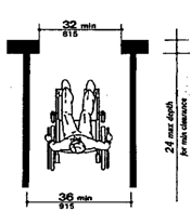
(1) Wheelchair Passage Width. The
minimum clear width for single wheelchair passage shall be 32 inches (815 mm)
at a point and 36 inches (915 mm) continuously (see Fig. l and 24(e)).
Fig. 1 Minimum Clear
Width for Single Wheelchair
Note: Space Requirements for Wheelchairs.
Many persons who use wheelchairs need a 30 inches
(760 mm) clear opening width for doorways, gates, and the like,
when the latter are entered head-on. If the person is
unfamiliar with a building, if competing traffic is heavy, if
sudden or frequent movements are needed, or if the wheelchair must be turned at
an opening, then greater clear widths are needed. For most situations, the
addition of an inch of leeway on either side is sufficient. Thus, a minimum
clear width of 32 inches
(815 mm) will provide adequate clearance. However, when an
opening or a restriction in a passageway is more than 24 in
(610 mm) long, it is essentially a passageway and must be at
least 36 inches (915 mm) wide.
(2) Space Requirements for Use
of Walking Aids. Although people who use walking aids can maneuver
through clear width openings of 32 in (815 mm) , they need 36 in
(915 mm) wide passageways and walks for comfortable gaits.
Crutch tips, often extending down at a wide angle, are a hazard in narrow
passageways where they might not be seen by other pedestrians. Thus, the 36
inches
(915 mm) width provides a safety allowance both for the person
with a disability and for others.
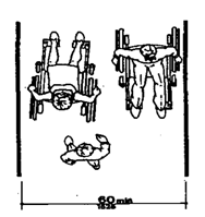
(3) Space Requirements for Passing.
Able-bodied persons in winter clothing, walking straight ahead with arms
swinging, need 32 inches (815 mm) of width, which includes 2 inches (50 mm) on
either side for sway, and another 1 inch (25 mm) tolerance on either side for
clearing nearby objects or other pedestrians. Almost all wheelchair users and
those who use walking aids can also manage within this 32 inches (815 mm) width
for short distances. Thus, two streams of traffic can pass in 64 inches (1625
mm) in a comfortable flow. Sixty inches (1525 mm) provides a minimum width for
a somewhat more restricted flow. If the clear width is less than 60 inches
(1525 mm) , two wheelchair users will not be able to pass but will have to seek
a wider place for passing. Forty-eight inches
(1220 mm) is the minimum width needed for an ambulatory person
to pass a non-ambulatory or semi-ambulatory person. Within this 48 inches (1220
mm) width, the ambulatory person will have to twist to pass a
wheelchair
Page 28
user, a person with a service animal, or a semi - ambulatory
person. There will be little leeway for swaying or missteps (see Fig. A1).
Fig. A1
Minimum
Passage Width for One Wheelchair and One Ambulatory Person
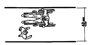
(2) Width for Wheelchair Passing. The minimum width for
two wheelchairs to pass is 60 inches (1525 mm) (see
Fig. 2).
Fig-2 Minimum Clear Width
for Two Wheelchairs
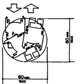
(3) Wheelchair Turning Space. The
space required for a wheelchair to make a 180-degree turn is a clear space
of 60 inches (1525 mm) diameter (see Fig.3(a)) or a T-shaped space
(see Fig. 3(b)).
Fig 3.3 (b)
T-Shaped Space for 180° turn
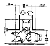
FIG. 3 (a)
60-In (1525-mm)-Diameter Space
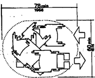
Note:
These
guidelines specify a minimum space of 60 inches (1525 mm) diameter or a 60
inches by 60 inches (1525 mm by 1525 mm) T-shaped space for a pivoting
180-degree turn of a wheelchair. This space is usually satisfactory for turning
around, but many people will not be able to turn without repeated tries and
bumping into surrounding objects. The space shown in Fig. A2 will allow most
wheelchair users to complete U-turns without difficulty.
Fig. A2
Space Needed for Smooth U-Turn in a
Wheelchair
Page 29
(4) Clear Floor or Ground Space for
Wheelchairs.
(a) Size and Approach. The
minimum clear floor or ground space required to accommodate a single,
stationary wheelchair and occupant is 30 inches by 48 inches (760 mm
by 1220 mm) (see Fig. 4(a)). The minimum clear floor or ground space for
wheelchairs may be positioned for forward or parallel approach to an object
(see Fig. 4(b) and (c)). Clear floor or ground space for wheelchair may be part
of the knee space required under some objects in the T-shape turn.
Note: The wheelchair and user shown in
Fig. A3 represent typical dimensions for a large adult male. The space
requirements in these rules are based upon maneuvering clearances that will
accommodate most wheelchairs. Fig. A3 provides a uniform reference for design
not covered by these rules.
NOTE: Footrests may extend further for tall people
Fig. A3
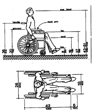
Fig. A3 (a)
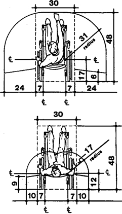
(b) Relationship of Maneuvering
Clearance to Wheelchair Spaces. One full unobstructed side
of the clear floor or ground space for a wheelchair shall adjoin or overlap an
accessible route or adjoin another wheelchair clear floor space. If a clear
floor space is located in an alcove or otherwise confined on all or part of
three sides, additional maneuvering clearances shall be provided as shown in
Fig. 4(d) and (e).
(c) Surfaces for Wheelchair Spaces. Clear
floor or ground spaces for wheelchairs shall comply with rule 120-3-20-16.
Page 30
Fig. 4
Minimum
Clear Floor Space for Wheelchairs
(a)
Clear Floor Space
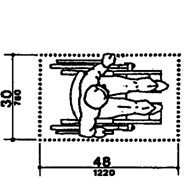
(b)
Forward Approach
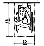
(c)
Parallel Approach
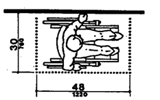
Clear Floor Space in Alcoves
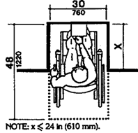
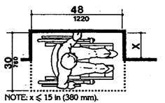
Additional Maneuvering Clearances for
Alcoves
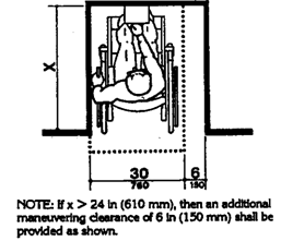
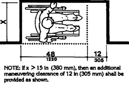
Page 31
FIG.5 (a)
High Forward Reach Limits
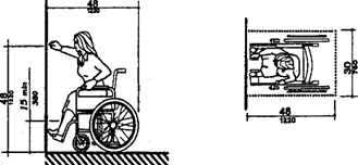
(5) Forward
Reach. If the clear floor space only allows forward
approach to an object, the maximum high forward reach allowed shall be 48
inches (1220 mm) (see Fig. 5(a)).
The minimum low forward reach is 15 inches (380 mm).
If the high forward reach is over an obstruction, reach and clearances shall be
as shown in Fig. 5(b).
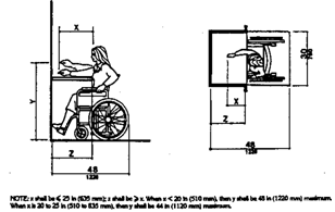
FIG. 5 (b) Maximum Forward Reach over an Obstruction
(6) Side Reach. If
the clear floor space allows parallel approach by a person in a wheelchair, the
maximum high side reach allowed shall be 54 inches (1370 mm) and the low side
reach shall be no less than 9 inches (230 mm) above the floor (Fig. 6(a) and
(b).
If the side reach is over an obstruction, the reach
and clearances shall be as shown in Fig. 6(c).
Note: Reach ranges for persons seated in
wheelchairs may be further clarified by Fig. A3(a). These drawings approximate
in the plan view the information shown in Fig. 4, 5, and 6.
120-3-20-.14 Accessible Route
(1) General. All
walks, halls, corridors, aisles, skywalks, tunnels, and other spaces that are
part of an accessible route shall comply with rule 120-3-20-. 14.
(2) Location.
(a) At least one
accessible route within the boundary of the site shall be provided from public
transportation stops, accessible parking, and accessible passenger loading
zones, and public streets or sidewalks to the accessible building entrance they
serve. The accessible route shall, to maximum extent feasible coincide with the
route for the general public.
Fig. 6 (c)
Side Reach
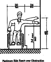
Fig. 6 (b) High and Low Side
Reach Limits
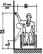
Page 32
(b) At least one
accessible route shall connect accessible buildings, facilities, elements, and
spaces that are on the same site.
(c) At least one
accessible route shall connect accessible building or facility entrances with
all accessible spaces and elements and with all accessible dwelling units
within the building or facility.
(d) An accessible
route shall connect at least one accessible entrance of each accessible
dwelling unit with those exterior and interior spaces and facilities that serve
the accessible dwelling unit.
Note:
Travel
Distances. Many people with mobility impairments can move at only very slow
speeds; for many, traveling 200 feet (61 m)
could take about 2 minutes. This assumes a rate of about 1.5 ft/s (455 mm/s) on
level ground. It also assumes that the traveler would move continuously.
However, on trips over 100 ft (30 m) , disabled people are apt to rest
frequently, which substantially increases their trip times. Resting periods of
2 minutes for every 100 ft (30 m) can be used to estimate travel times for
people with severely limited stamina. In inclement weather, slow progress and
resting can greatly increase a disabled person's exposure to the elements.
(2) Sites.
Level, indirect
routes or those with running slopes lower than 1:20 can
sometimes provide more convenience than direct routes with maximum
allowable slopes or with ramps.
(3) Width. The
minimum clear width of an accessible route shall be 36 inches (915 mm) except
at doors (see rule 120-3-20-.24 (5) and rule 120-3-20-.24(6). If a person in a
wheelchair must make a turn around an obstruction, the minimum clear width of
the accessible route shall be as shown in Fig. 7(a) and (b).
Fig. 7 (a)
90° Turn
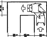
Fig. 7 (b)
Turn around an Obstruction
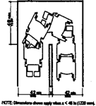
(4) Passing Space. If an accessible route has
less than 60 inches (1525 mm) clear width, then passing spaces at least 60
inches by 60 inches (1525 mm by 1525 mm) shall be located at reasonable
intervals not to exceed 200 feet (61 m). A T-intersection of two corridors or
walks is an acceptable passing place.
(5) Head Room.
Accessible route shall comply with rule
120-3-20-.15.
(6) Surface Texture.
Surface textures of an accessible route shall comply
with rule 120-3-20-.16.
FIG. 3 (b)
T-Shaped Space for 180° Turns
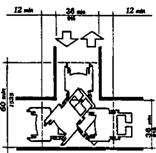
Page 33
(7) Slope. All accessible route with running
slopes greater than 1:20 is a ramp and shall comply with rule
120-3-20-.19. Cross slope shall not exceed 1:50.
(8) Changes in Level. Changes in level along
an accessible route shall comply with 120-3-20-.16. If an accessible route has
changes in level greater than 1/2 inch (13 mm), then a curb ramp, ramp,
elevator, or platform lift (as permitted in rules 120-3-20-.08 and 120-3-20-.11
shall be provided that complies with rules 120-3-20-.18, 120-3-20-.19,
120-3-20-.21,or 120-3-20-.22, respectively. Accessible route does not include
stairs, steps, or escalators. See definition of "egress, means of in rule
120-3-20-.06.
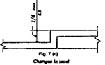
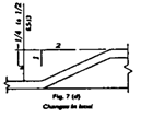
(9) Doors. Doors
that are part of an accessible route shall comply with 120-3-20-.24.
(10) Egress. Accessible
routes serving any accessible space or element shall also serve as a means of
egress for emergencies or connect to an accessible area of rescue assistance.
Note: Because people with disabilities
may visit, be employed or be a resident in any building, emergency
management plans with specific provisions to ensure their safe evacuation also
play an essential role in fire safety and life safety.
(11) Areas of Rescue Assistance.
(a) Location and
Construction. An area of rescue assistance shall be one of the following:
1. A portion of a
stairway landing within a smokeproof enclosure (complying with local
requirements).
2. A portion of an
exterior exit balcony located immediately adjacent to an exit stairway when the
balcony complies with local requirements for exterior exit balconies. Openings
to the interior of the building located within 20 feet (6 m) of the area of
rescue assistance shall be protected with fire assemblies having a
three-fourths hour fire protection rating.
3. A portion of a
one-hour fire-resistive corridor (complying with local requirements for
fire-resistive construction and for openings) located immediately adjacent to
an exit enclosure.
4. A vestibule
located immediately adjacent to an exit enclosure and constructed to the same
fire-resistive standards as required for corridors and openings.
5. A portion of a
stairway landing within an exit enclosure which is vented to the exterior and
is separated from the interior of the building with not less than one-hour
fire-resistive doors.
6. When approved by
the appropriate local authority, an area or a room which is separated from
other portions of the building by a smoke barrier. Smoke barriers shall have a
fire-resistive rating of not less than one hour and shall completely enclose
the area or room. Doors in the smoke barrier shall be tight-fitting
smoke-control and draft-control assemblies having a fire-protection rating of
not less than 20 minutes and shall be self-closing or automatic closing. The
area or room shall be provided with an exit directly to an exit enclosure.
Where the room or area exits into an exit enclosure which is required
Page 34
to be of more than one-hour fire-resistive
construction, the room or area shall have the same fire-resistive construction,
including the same opening protection, as required for the adjacent exit
enclosure.
7. An elevator lobby when elevator shafts and
adjacent lobbies are pressurized as required for smokeproof enclosures by local
regulations and when complying with requirements herein for size,
communication, and signage. Such pressurization system shall be activated by
smoke detectors on each floor located in a manner approved by the appropriate
local authority. Pressurization equipment and its duct work within the building
shall be separated from other portions of the building by a minimum two-hour
fire-resistive construction.
(b) Size. Each
area of rescue assistance shall provide at least two accessible areas each
being not less than 30 inches by 48 inches (760 mm by 1220 mm). The area of
rescue assistance shall not encroach on any required exit width. The total
number of such 30-inches by 48-inches (760 mm by 1220 mm) areas per story shall
be not less than one for every 200 persons of calculated occupant load
served by the area of rescue assistance.
EXCEPTION: The
appropriate local authority may reduce the minimum number of 30-inches by
48-inches (760 mm by 1220 mm) areas to one for each area of rescue assistance
on floors where the occupant load is less than 200.
(c) Stairway Width. Each
stairway adjacent to an area of rescue assistance shall have a minimum clear
width of 48 inches between handrails.
Note:
A
48 inches (1220 mm) wide exit stairway is needed to allow assisted evacuation
(e.g., carrying a person in a wheelchair) without encroaching on the exit path
for ambulatory persons.
(d) Two-way Communication. A
method of two-way communication, with both visible and audible signals, shall
be provided between each area of rescue assistance and the primary entry. The
fire department or appropriate local authority may approve a location other
than the primary entry.
Note:
It
is essential that emergency communication not be dependent on voice
communications alone because the safety of people with hearing or speech
impairments could be jeopardized. The visible signal requirement could be
satisfied with something as simple as a button in the area of rescue assistance
that lights, indicating that help is on the way, when the message is answered
at the point of entry.
(e) Identification. Each area of rescue
assistance shall be identified by a sign which states "AREA OF
RESCUE ASSISTANCE" and displays the international symbol of
accessibility. The sign shall be illuminated when exit sign illumination is
required. Signage shall also be installed at all inaccessible exits and where
otherwise necessary to clearly indicate the direction to areas of rescue
assistance. In each area of rescue assistance, instructions on the use of the
area under emergency conditions shall be posted adjoining the two-way
communication system.
Page 35
120-3-20-.15 Protruding
Objects
(1) General. Objects
projecting from walls (for example, telephones) with their leading edges
between 27 inches and 80 inches (685 mm and 2030 mm) above the finished floor
shall protrude no more than 4 inches (100 mm) inches to walks, halls,
corridors, passageways, or aisles (see Fig. 8(a)). Objects mounted with their
leading edges at or below 27 inches (685 mm) above the finished floor may
protrude any amount (see Fig. 8(a) and (b)). Free-standing objects mounted on
posts or pylons may overhang 12 inches (305 mm)
maximum from 27 inches to 80 inches (685 mm to 2030
mm) above the ground or finished floor (see Fig. 8(c) and (d)). Protruding
objects shall not reduce the clear width of an accessible route
or maneuvering space (see Fig. 8(e)).
Note: General. Service animals are
trained to recognize and avoid hazards. However, most people with severe
impairments of vision use the long cane as an aid to mobility. The two
principal cane techniques are the touch technique, where the cane
arcs from side to side and touches points outside both shoulders; and
the diagonal
technique, where the cane is held in a stationary position
diagonally across the body with the cane tip touching or just
Fig. 8 (a) Walking Parallel to a Wall
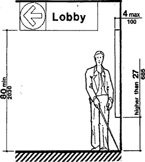
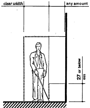
Page 36
Fig. 8 (c) Free-Standing Overhanging
Objects
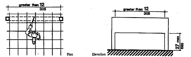
Fig.
8 (c-1) Overhead Hazards
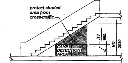
Fig. a (b) Walking Perpendicular to a
Wall
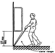
Fig. 8 (d) Objects Mounted on Posts or
Pylons
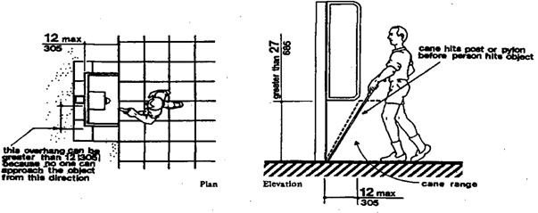
Page 37
above the ground at a point outside one shoulder and the handle
or grip extending to a point outside the other shoulder. The touch technique is
used primarily in uncontrolled areas, while the diagonal technique is used
primarily in certain limited, controlled, and familiar environments. Cane users
are often trained to use both techniques.
Potential hazardous objects are noticed only if they fall within
the detection range of canes.
(see Fig. A4). Visually impaired people walking toward an object
can detect an overhang if its lowest surface is not higher than 27 inches (685
mm) . When walking alongside protruding objects, they cannot detect overhangs .
Since proper cane and service animal techniques keep people away from the edge
of a path or from walls, a slight overhang of no more than 4 inches (100 mm) is
not hazardous.
Fig. A4 Cane
Technique
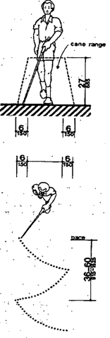
(2) Head Room. Walks,
halls, corridors, passageways, aisles, or other circulation spaces shall have
80 inches (2030 mm) minimum clear head room (see Fig. 8(a)).
If vertical clearance of an area adjoining an accessible route
is reduced to less than 80 inches (nominal dimension), a barrier to warn blind
or visually-impaired persons shall be provided(see Fig. 8(c-l)).
120-3-20-.16 Ground and Floor Surfaces
(1) General.
Ground
and floor surfaces along accessible routes and in accessible rooms and spaces
including floors, walks, ramps, stairs, and curb ramps, shall be stable, firm,
slip-resistant, and shall comply with rule 120-3-20.19.
Note: People who have difficulty walking
or maintaining balance or who use crutches, canes, or walkers, and those with
restricted gaits are particularly sensitive to slipping and tripping
hazards. For such
people, a stable and regular surface is necessary for safe
walking, particularly on stairs. Wheelchairs can be propelled most easily on
surfaces that are hard, stable, and regular. Soft loose surfaces such as shag
carpet, loose sand or gravel, wet clay, and irregular surfaces such as cobblestones
can significantly impede wheelchair movement.
Page 38
Slip resistance is based on the frictional force necessary to
keep a shoe heel or crutch tip from slipping on a walking surface under
conditions likely to be found on the surface. While the dynamic
coefficient of friction during walking varies in a complex and non-uniform way,
the static coefficient of friction, which can be measured in several
ways, provides a close approximation of the slip resistance of a surface.
Contrary to popular belief, some slippage is necessary to walking,
especially for persons with restricted gaits; a truly "non-slip"
surface could not be negotiated.
The Occupational Safety and Health Administration recommends
that walking surfaces have a static coefficient of friction of 0.5. A
research project
sponsored by the Architectural and Transportation Barriers
Compliance Board (Access Board) conducted tests with persons with disabilities
and concluded that a higher coefficient of friction was needed by such persons.
A static coefficient of friction of 0.6 is recommended for accessible routes
and 0.8 for ramps.
It is recognized that the coefficient of friction varies
considerably due to the presence of contaminants, water, floor finishes, and
other factors not under the control of the designer or builder and not
subject to design and construction guidelines and that compliance would be
difficult to measure on the building site. Nevertheless, many common building
materials suitable for flooring are now labeled with information on the static
coefficient of friction. While it may not be possible to compare one product
directly with another, or to guarantee a constant measure, builders and
designers are encouraged to specify materials with appropriate values. As more
products include information on slip resistance, improved uniformity in
measurement and specification is likely. The Access Board's advisory
guidelines on Slip Resistant Surfaces provides additional
information on this subject.
Cross slopes on walks and ground or floor surfaces can cause
considerable difficulty in propelling a wheelchair in a straight line.
(2) Changes
in Level. Changes in level up to 1/4 inches (6 mm) may be
vertical and without edge treatment (see Fig. 7(c) ). Changes in level between
1/4 inches and 1/2 inches (6 mm and 13 mm) shall be beveled with a slope
no greater than 1:2 (see Fig. 7(d)). Changes in level greater than 1/2 inches
(13 mm) shall be accomplished by means of a ramp that complies with 120-3-20-.
18 or l20-3-20-.19
Page 39
Fig. 7 (c)
Changes in level
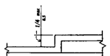
Fig. 7 (d)
Changes in level
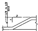
(3) Carpet. If
carpet or carpet tile is used on a ground or floor surface, then it shall be
securely attached; have a firm cushion, pad, or backing, or no cushion or pad;
and have a level loop, textured loop, level cut pile, or level cut/uncut pile
texture. The maximum pile thickness shall be 1/2 inches (13 mm)(see Fig. 8(f)).
Exposed edges of carpet shall be fastened to floor surfaces and have trim along
the entire length of the exposed edge. Carpet edge trim shall comply with rule
120-3-20-.16(2).
Fig. 8 (f) Carpet Pile Thickness
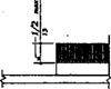
Note: Much more needs to be done in
developing both quantitative and qualitative criteria for carpeting (i.e.,
problems associated with texture and weave need to be studied) . However,
certain functional characteristics are well established. When both carpet and
padding are used, it is desirable to have minimum movement (preferably
none)
between the floor and the pad and the pad and the carpet which
would allow the carpet to hump or warp. In heavily trafficked areas, a thick,
soft (plush) pad or cushion, particularly in combination with long
carpet pile, makes it difficult for individuals in wheelchairs and those with
other ambulatory disabilities to get about. Firm carpeting can be achieved
through proper selection and combination of pad and carpet, sometimes with the
elimination of the pad or cushion, and with proper installation. Carpeting
designed with a weave that causes a zig-zag effect when wheeled across is
strongly discouraged.
(4) Gratings. If
gratings are located in walking surfaces, then they shall have spaces no
greater than l1/2 inches (13 mm) wide in one direction (see Fig.
8(g)). If gratings have elongated openings, then they shall be placed so that
the long dimension is perpendicular to the dominant direction of travel (see
Fig. 8(h)).
Fig.8(g)
Gratings
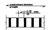
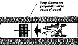
Fig. 8(h) Grating Orientation
Page 40
120-3-20-.17 Parking and Passenger
Loading Zones
(1) Minimum Number. Parking
spaces required to be accessible by rule 120-3-20-.07 shall comply with rules
120-3-20-.17(2) through 120-3-20-.17(5). Passenger loading zones required to be
accessible by rule 120-3-20-.07 shall comply with rules 120-3-20-.17(5) and
120-3-20-.17(6).
(2) Location. Accessible
parking spaces serving a particular building shall be located on the shortest
accessible route of travel from adjacent parking to an accessible entrance. In
parking facilities that do not serve a particular building, accessible parking
shall be located on the shortest accessible route of travel to an accessible
pedestrian entrance of the parking facility. In buildings with multiple
accessible entrances with adjacent parking, accessible parking spaces shall be
dispersed and located closest to the accessible entrances.
(3) Parking Spaces. Accessible
parking spaces shall be at least 96 inches (2440 mm) wide. Parking access
aisles shall be part of an accessible route to the building or facility
entrance and shall comply with rule 120-3-20-.14. Two accessible parking spaces
may share a common access aisle (see Fig.9). Parked vehicle overhangs shall not
reduce the clear width of an accessible route.
Fig. 9
Dimensions of Parking Spaces
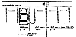
Parking spaces
and access aisles shall be level with surface slopes not
exceeding 1:50 (2%) in all directions.
Note: The increasing
use of vans with side-mounted lifts or ramps by persons with disabilities has
necessitated some revisions in specifications for parking spaces and adjacent
access aisles. The typical accessible parking space is 96 inches (2440 mm) wide
with an adjacent 60 inches (1525 mm) access aisle. However, this aisle does not
permit lifts or ramps to be deployed and still leave room for a person using a
wheelchair or other mobility aid to exit the lift platform or ramp. In tests
conducted with actual lift/van/wheelchair combinations, (under a
Board-sponsored Accessible Parking and Loading Zones Project) researchers found
that a space and aisle totaling almost 204 inches (5180 mm) wide was needed to
deploy a lift and exit conveniently. The "van accessible" parking
space required by these rules provides a 96 inches (2440 mm) wide space with a
96 inches (2440 mm) adjacent access aisle which is just wide enough to maneuver
and exit from a side mounted lift. If a 96 inches (2440 mm) access aisle is
placed between two spaces, two "van accessible" spaces are created.
Alternatively, if the wide access aisle is provided at the end of a row (an
area often unused), it may be possible to provide the wide access aisle without
additional space (see Fig. A5(a)).
(a)
Van Accessible Space at End Row
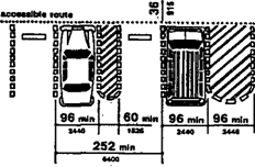
Page 41
A sign is needed to alert van users to the
presence of the wider aisle, but the space is not intended to be
restricted only to vans.
"Universal" Parking Space
Design. An
alternative to the provision of a percentage of
spaces with a wide aisle, and the associated need to include additional
signage, is the use of what has been called the "universal" parking
space design. Under this design, all accessible spaces are 132 inches (3350 mm)
wide with a 60 inches (1525 mm) access aisle (see Fig. A5(b)). One advantage to
this design is that no additional signage is needed because all spaces can
accommodate a van with a side-mounted lift or ramp. Also, there is no
competition between cars and vans for spaces since all spaces can accommodate
either. Furthermore, the wider space permits vehicles to park to one side or the
other within the 132 inches (3350 mm) space to
allow persons to exit and enter the vehicle on
either the driver or passenger side, although, in some cases, this would
require exiting or entering without a marked access aisle.
(b)
Universal Parking Space Design
Fig. A5 Parking Space
Alternatives
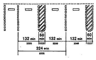
An essential consideration for any design is having
the access aisle level with the parking space. Since a person with a
disability, using a lift or ramp, must maneuver within the access aisle, the
aisle cannot include a ramp or sloped area. The access aisle must be connected
to an accessible route to the appropriate accessible entrance of a building or
facility. The parking access aisle must either blend with the accessible route
or have a curb ramp complying with rule 120-3-20-. 18. Such a curb ramp opening
must be located within the access aisle boundaries, not within the parking
space boundaries. Unfortunately, many facilities are designed with a ramp that
is blocked when any vehicle parks in the accessible space. Also, the required
dimensions of the access aisle cannot be restricted by planters, curbs or wheel
stops.
(4) Signage.
Accessible parking spaces shall be designated as reserved by a sign complying
with 120-3-20.41(7) and the following:
O.C.G.A. 40-6-221 Provide a blue metal
reflective sign which is at least 12" inches width and 18" inches
length and is erected at 60" from ground to bottom of the sign
in such a manner that it will not be obscured by a vehicle parked in the
space and bearing the international symbol for accessibility. The
warning required in this subparagraph shall be centered on the sign,
printed in white, and shall occupy not less than 75 % of the sign.
Spaces complying with rule 120-3-20-.07(e)(2) shall
have an additional sign stating "Van-Accessible" mounted below the
symbol of accessibility.
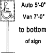
Page 42
Such signs shall be located so they cannot be obscured
by a vehicle parked in the space. The bottom of signs for accessible autos
parking spaces hall be at least 60 inches above grade and 72 inches for
accessible van parking spaces.
Note: Signs designating parking places
for disabled people can be seen from a driver's seat if the signs are mounted
high enough above the ground and located at the front of a parking space.
(5) Vertical Clearance. Provide
minimum vertical clearance of 114 inches (2895 mm) at accessible
passenger loading zones and along at least one vehicle access route to such
areas from site entrance(s) and exit(s). At parking spaces complying with rule
120-3-20-.07(e)(2), provide minimum vertical clearance of 98 inches (2490
mm) at the parking space and along at least one vehicle access route
to such spaces from site entranced and exit(s).
Note: High-top vans,
which disabled people or transportation services often use, require higher
clearances in parking garages than automobiles.
Fig. 10
Access Aisle at Passenger Loading Zones
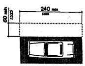
(6) Passenger Loading Zones. Passenger
loading zones shall provide an access aisle at least 60 inches (1525 mm) wide
and 20 feet (240 inches)(6100 mm) long adjacent and parallel to the vehicle
pull-up space (see Fig. 10). If there are curbs between the access aisle and
the vehicle pull-up space, then a curb ramp complying with rule 120-3-20-.18
shall be provided. Vehicle standing spaces and access aisles shall be
level with surface slopes not exceeding 1:50 (2%) in
all directions.
120-3-20-.18 Curb Ramps
(1) Location. Curb
ramps complying with 120-3-20-. 18 shall be provided wherever an accessible
route crosses a curb.
(2) Slope. Slopes
of curb ramps shall comply with rule 120-3-20-.19. The slope shall be measured
as shown in Fig. 11.
Fig. 11
Measurement of Curb Ramp Slopes
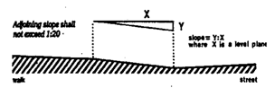
Transitions from ramps to walks, gutters, or streets
shall be flush and free of abrupt changes. Maximum slopes of adjoining gutters,
road surface immediately adjacent to the curb ramp, or accessible route shall
not exceed 1:20.
(3) Width. The
minimum width of a curb ramp shall be 36 inches (915 mm), exclusive of
flared sides.
(4) Surface. Surfaces
of curb ramps shall comply with rule 120-3-20-.16.
Page 43
Fig. 12 Sides of Curb Ramps
(a)
Flared
Sides
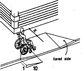
(b)
Returned Curb
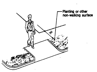
If X is less than 48 in,
then the slope of the flared side
shall not exceed 1:12.
(5) Sides
of Curb Ramps. If a curb ramp is located where
pedestrians must walk across the ramp, or where it is not protected by
handrails or guardrails, it shall have flared sides; the maximum
slope of the flare shall be 1:10 (see Fig. 12(a)). Curb ramps with returned
curbs may be used where pedestrians would not normally walk across the ramp
(see Fig. 12(b)).
(6) Built-up Curb Ramps. Built-up curb ramps
shall be located so that they do not project into vehicular traffic lanes (see
Fig. 13).
(7) Detectable
Warnings. A curb ramp shall have a detectable warning
complying with rule 120-3-20-.40. The detectable warning shall extend
the full width and depth of the curb ramp, including flares.
(8) Obstructions. Curb
ramps shall be located or protected to prevent their obstruction by parked
vehicles.
(9) Location at Marked Crossings. Curb
ramps at marked crossings shall be wholly contained within the markings,
excluding any flared sides (see Fig. 15). Such signs shall be located so they
cannot be obscured by a vehicle parked in the space.
The bottom of signs for accessible autos parking
Fig. 13 Built-Up Curb Ramp
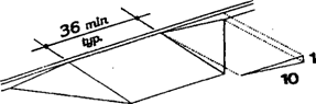
Page 44
spaces shall be at least 60 inches above
grade and 72 inches for accessible van parking spaces.
Note:
Signs
designating parking places for disabled people can be seen from a driver's seat
if the signs are mounted high enough above the ground and located at the front
of a parking space.
(5) Vertical Clearance. Provide
minimum vertical clearance of 114 inches (2895 mm) at accessible
passenger loading zones a^ along at least one vehicle access route to such
areas from site entrance(s) and exit(s). At parking spaces complying with rule
120-3-20-.07(5)(b), provide minimum vertical clearance of 98 inches (2490
mm) at the parking space and along at least one vehicle access route
to such spaces from site entranced and exit(s).
Note: High-top vans,
which disabled people or transportation services often use, require higher
clearances in parking garages than automobiles.
Fig. 10
Access Aisle at Passenger Loading Zones
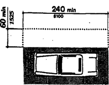
(6) Passenger Loading Zones. Passenger
loading zones shall provide an access aisle at least 60 inches (1525 mm) wide
and 20 feet (240 inches)(6100 mm) long adjacent and parallel to the vehicle
pull-up space (see Fig. 10). If there are curbs between the access aisle and
the vehicle pull-up space, then a curb ramp complying with 120-3-20-.18 shall
be provided. Vehicle standing spaces and access aisles shall
be level with surface slopes not exceeding 1:50 (2%) in
all directions.
120-3-20-.18 Curb Ramps.
(1) Location. Curb
ramps complying with rule 120-3-20-.18 shall be provided wherever an accessible
route crosses a curb.
(2) Slope. Slopes
of curb ramps shall comply with rule 120-3-20-.19. The slope shall be measured
as shown in Fig. 11.
Fig. 11
Measurement of Curb
Ramp Slopes
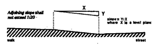
Transitions from ramps to walks, gutters, or streets
shall be flush and free of abrupt changes. Maximum slopes of adjoining gutters,
road surface immediately adjacent to the curb ramp, or accessible route shall not
exceed 1:20.
(3) Width. The
minimum width of a curb ramp shall be 36 inches (915 mm), exclusive of
flared sides.
(4) Surface. Surfaces of curb ramps shall
comply with rule 120-3-20-.16.
Page 45
(10) Diagonal Curb Ramps. If
diagonal (or corner type) curb ramps have returned curbs or other well-defined
edges, such edges shall be parallel to the direction of pedestrian flow. The
bottom of diagonal curb ramps shall have 48 inches (1220 mm) minimum clear
space as shown in Fig. 15(c) and (d). If diagonal curb ramps are provided at
marked crossings, the 48 inches (1220 mm) clear space shall be within the
markings (see Fig. 15(c) and (d)). If diagonal curb ramps have flared sides,
they shall also have at least a 24 inches (610 mm) long segment of straight
curb located on each side of the curb ramp and within the marked crossing (see Fig.
15(c)).
(11) Islands.
Any
raised islands in crossings shall be cut through level with the street or have
curb ramps at both sides and a level area at least 48 inches (1220 mm) long
between the curb ramps in the part of the island intersected by the crossings
(see Fig. 15(a) and (b)).
Fig. 15
Curb Ramps at Marked Crossings
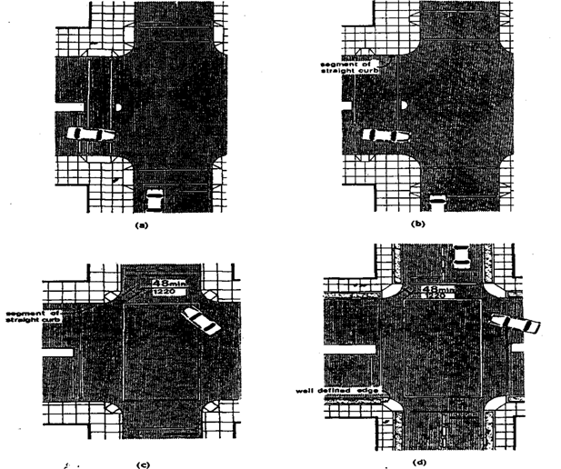
Page 46
120-3-20-.19 Ramps
(1) General. Any
part of an accessible route with a slope greater than 1:20 shall be
considered a ramp and shall comply with rule 120-3-20-.19.
Note: Ramps are essential for wheelchair
users if elevators or lifts are not available to connect different levels.
However, some people who use walking aids have difficulty with ramps and prefer
stairs.
Fig.16
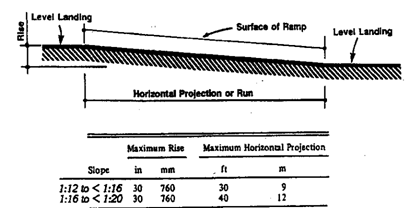
(2) Slope and Rise. The
least possible slope shall be used for any ramp. The maximum
slope of a ramp in new construction shall be 1:12. The maximum rise for
any run shall be 30 inches (760 mm) (see Fig. 16).
Curb ramps and ramps to be constructed on existing
sites or in existing buildings or facilities may have slopes and rises as
allowed in rule 120-3-20-.11 (3) (a) if space limitations prohibit the use of a
1:12 slope or less.
Note: Ramp slopes between 1:16 and 1:20
are preferred. The ability to manage an incline is
related to both its slope and its length. Wheelchair
users with disabilities affecting their arms or with low stamina have serious
difficulty using inclines. Most ambulatory people and most people who use
wheelchairs can manage a slope of 1:16. Many
people cannot manage a slope of 1:12 for 30 feet
(9m).
(3) Clear Width. The
minimum clear width of a ramp shall be 36 inches (915 mm).
(4) Landings. Ramps shall have level
landings at bottom and top of each ramp and each ramp run. Landings shall
have the following features:
(a) The landing
shall be at least as wide as the ramp run leading to it.
(b) The landing length shall be a minimum of 60
inches (1525 mm) clear.
(c) If ramps change
direction at landings, the minimum landing size shall be 60 inches by 60
inches (1525 mm by 1525 mm).
(d) If a doorway is
located at a landing, then the area in front of the doorway shall comply with
rule 120-2-20-.24(6).
Note: Level landings
are essential toward maintaining an aggregate slope that complies with these
rules. A ramp landing that is not level causes individuals using wheelchairs to
tip backward or bottom out when the ramp is approached.
Page 47
(5) Handrails. If
a ramp run has a rise greater than 6 inches (150 mm) or a horizontal projection
greater than 72 inches (1830 mm), then it shall have handrails on both sides.
Handrails are not required on curb ramps or adjacent to seating in assembly
areas. Handrails shall comply with rule 120-3-20-.37 and shall have the
following features:
(a) Handrails shall
be provided along both sides of ramp segments. The inside handrail on
switchback or dogleg ramps shall always be continuous.
(b) If handrails are
not continuous, they shall extend at least 12 inches (305 mm) beyond the
top and bottom of the ramp segment and shall be parallel with the
floor or ground surface (see Fig. 17).
(c) The clear space
between the handrail and the wall shall be 1 1/2 inches (38
mm).
(d) Gripping surfaces
shall be continuous, without interruption by
newel posts, other construction elements, or obstructions.
(e) Handrails shall
have a circular cross section with an outside diameter of 1 1/4 inches (32
mm) minimum and 1 1/2 inches (51 mm) maximum.
(f) Handrails,
and any wall or other surfaces adjacent to them, shall be free of any sharp or
abrasive elements. Edges shall have 1/8 inches (3.2 mm) minimum radius.
(g) Top of
handrail gripping surfaces shall be mounted between 34 inches and 38 inches (865
mm and 965 mm) above ramp surfaces.
Fig. 17
Examples of Edge Protection and Handrail Extensions
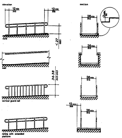
(h) Ends of
handrails shall be either rounded or returned smoothly to floor, wall, or post.
(i) Handrails shall
not rotate within their fittings.
Note: The requirements for stair and ramp
handrails in these rules are for adults. When children are principal users in a building or facility, a second set of handrails an appropriate height is required to assist them and aid in preventing
accidents.
Page 48
(6) Cross Slope and Surfaces. The
cross slope of ramp surfaces shall be no greater than 1:50. Ramp
surfaces shall comply with rule 120-3-20-.16.
(7) Edge Protection. Ramps and landings with
drop-offs shall have curbs, walls, railings, or projecting surfaces that
prevent people from slipping off the ramp. Curbs shall be a minimum
of 2 inches (50 mm) high (see Fig. 17).
(8) Outdoor Conditions. Outdoor
ramps and their approaches shall be designed so that water will not accumulate
on walking surfaces.
120-3-20-.20 Stairs
(1) Minimum Number. Stairs required to be
accessible by rule 120-3-20-.03 shall comply with rule 120-3-20-.20.
Note: Only interior and exterior stairs
connecting levels that are not connected by an elevator, ramp, or other
accessible means of vertical access have to comply with rule 120-3-20-.20.
(2) Treads and Risers. On
any given flight of stairs, all steps shall have uniform riser heights and
uniform tread widths. Stair treads shall be no less than 11 inches (280 mm)
wide, measured from riser to riser (see Fig. 18(a)).
Open risers are not permitted.
Fig. 18 (b)
Angles Nosing
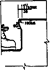
(3) Nosing. The
underside of nosing shall not be abrupt. The radius of curvature at the leading
edge of the tread shall be no greater than 1/2 inch (13 mm). Risers
shall be sloped or the underside of the nosing shall have an angle not less
than 60 degrees from the horizontal. Nosing shall project no more than 1-1/2
inches (38 mm) (see Fig. 18(a)).
Fig. 18 (a)
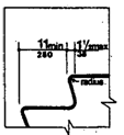
(4) Handrails. Stairways shall have handrails
at both sides of all stairs. Handrails shall comply with 4.26 and shall have
the following features:
(a) Handrails shall
be continuous along both sides of stairs. The inside handrail on switchback or
dogleg stairs shall always be continuous (see Fig. 19(a) and (b)).
Fig. 19 (a) Plan
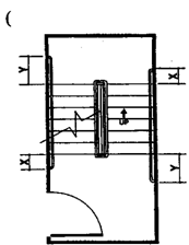
Fig. 19(b) Elevation of Center
Handrail
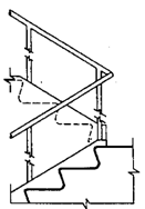
If handrails are not continuous, they shall extend
at 12 inches (305 mm) minimum beyond the top riser and at least 12 inches (305
mm) plus the width of one tread beyond the bottom riser. At the top, the
extension shall be parallel with the floor or ground surface. At the bottom,
the handrail shall continue to slope for a distance of the width of one tread
from the bottom riser; the remainder of the extension shall be horizontal (see
Fig. 19 (c)).
Page 49
Handrail extensions shall comply with rule
120-3-20-.15.
Fig. 19 (d) Extension at Top of Run
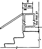
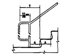

(c) The clear space
between the handrail and the wall shall be 1 1/2 inches (38 mm).
(d) Gripping
surfaces shall be continuous, without interruption by newel posts, other
construction elements, or obstructions.
(e) Handrails shall
have a circular cross section with an outside diameter of 1
1/4 inches (32 mm) minimum and 1 1/2 inches (51 mm)
maximum.
Fig. 39(a) Handrail
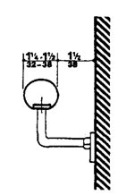
(f) Handrails, and
any wall or other surfaces adjacent to them, shall be free of any sharp or
abrasive elements. Edges shall have 1/8 inches (3.2 mm) minimum
radius.
(g) Top of handrail
gripping surfaces shall be mounted between 34 inches and 38 inches (865
mm and 965 mm) above stair nosing.
(h) Ends of
handrails shall be either rounded or returned smoothly to floor, wall, or post.
(i) Handrails shall
not rotate within their fittings.
(J) The design of
guards and handrails and the hardware for attaching handrails to guards,
balusters, or walls shall be such that there are no projections that may
engage loose clothing. Openings in guards shall be designed to prevent
loose clothing from becoming wedged in such openings.
(5) Detectable Warnings at Stairs.
(1) General. Detectable
warning shall comply with rule 120-3-20-.40(4).
(2) Detectable Warning at Stairs. All stairs,
except those in dwelling units, in enclosed stair towers, or set to side of the
path of travel shall have a detectable warning at the top of the each stair
run. (See Fig.41)
Fig. 41 Textile Warning at
Stairs
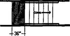
Fig. 40
Strips and Grooves used as Tactile
Warnings on Walking Surfaces
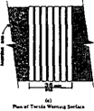
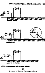
Page 50
120-3-20-.21 Elevators
(1) General. Accessible
elevators shall be on an accessible route and shall comply with rule
120-3-20-.21 and with the ASME A17.1-1990, Safety Code for Elevators and
Escalators. Freight elevators shall not be considered as meeting the
requirements of this section unless the only elevators provided are used as
combination passenger and freight elevators for the public and employees.
(2) Automatic Operation. Elevator
operation shall be automatic. Each car shall be equipped with a self-leveling
feature that will automatically bring the car to floor landings within a
tolerance of 1/2 inches (13 mm) under rated loading to zero
loading conditions. This self-leveling feature shall be automatic and
independent of the operating device and shall correct the over travel or under
travel.
Fig. 20
Hoistway and Elevator Entrances
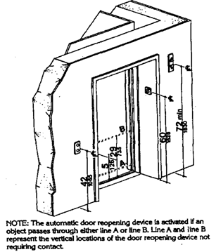
(3) Hall Call Buttons. Call
buttons in elevator lobbies and halls shall be centered at 42 inches (1065
mm) above the floor. Such call buttons shall have visual signals to indicate
when each call is registered and when each call is answered. Call buttons shall
be a minimum of 3/4 inch (19 mm) in the smallest dimension. The button
designating the up direction shall be on top. (See Fig. 20.) Buttons shall be
raised or flush. Objects mounted beneath or placed in front ofthe
hall call buttons shall not protect into the elevator lobby more
than 4 inches (100 mm).
(4) Hall Lanterns. A
visible and audible signal shall be provided at each hoist way entrance to
indicate which car is answering a call. Audible signals shall sound once for
the up direction and twice for the down direction or shall have verbal
annunciators that say "up" or "down."
Visible signals shall have the following
features:
(a) Hall lantern
fixtures shall be mounted so that their centerline is at least 72 inches (1830
mm) above the lobby floor. (See Fig. 20.)
(b) Visual elements
shall be at least 2-1/2 inches (64 mm) in the smallest dimension.
(c) Signals shall be
visible from the vicinity of the hall call button (see Fig. 20). In-car
lanterns located in cars, visible from the vicinity of hall call buttons, and
conforming to the above requirements, shall be acceptable.
(5) Raised and Braille Characters on
Hoist way Entrances. All elevator hoist way entrances shall
have raised and Braille floor designations provided on both jambs. The centerline
of the characters shall be 60 inches (1525 mm) above finish
floor. Such characters shall be 2 inches
Page 51
(50 mm) high and shall comply with rule
120-3-20-.41(4). Permanently applied plates are acceptable if they are
permanently fixed to the jambs. (See Fig. 20).
(6) Door Protective and Reopening
Device. Elevator doors shall open and close automatically.
They shall be provided with a reopening device that will stop and reopen a car
door and hoist way door automatically if the door becomes obstructed by an
object or person. The device shall be capable of completing these operations
without requiring contact for an obstruction passing through the opening at
heights of 5 inches and 29 inches (125 mm and 735 mm) above finish floor (see
Fig. 20). Door reopening devices shall remain effective at least 20 seconds.
Note: The required door reopening device
would hold the door open for 20 seconds if the doorway remains obstructed.
After 20 seconds, the door may begin to close. However, if designed in
accordance with ASME A17.1-1990, the door closing movement could still be
stopped if a person or object exerts sufficient force at any point on the door edge.
(7) Door and Signal Timing for Hall Calls.
The minimum acceptable time from notification that a
car is answering a call until the doors of that car start to close shall be
calculated from the following equation:
T = D/(1.5
ft/s) or T = D/(445 mm/s)
where T total time in seconds and D distance
(in feet or millimeters) from a point in the lobby or corridor 60 inches (1525
mm) directly in front of the farthest call button controlling that car to the
centerline of its hoist way door (see Fig. 21). For cars with in-car lanterns, T
begins when the lantern is visible from the vicinity of hall call buttons
and an audible signal is sounded. The minimum acceptable notification time
shall be 5 seconds.
Fig. 21 Graph of Timing Equation
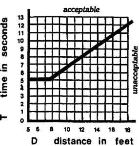
Note: This paragraph allows variation in
the location of call buttons, advance time for warning signals, and the
door-holding period used to meet the time requirement.
(8) Door Delay for Car Calls. The minimum
time for elevator doors to remain fully open in response to a car call shall be
3 seconds.
Page 52
(9) Floor Plan of Elevator Cars. The
floor area of elevator cars shall provide space for wheelchair users to enter
the car, maneuver within reach of controls, and exit from the car. Acceptable
door opening and inside dimensions shall be as shown in Fig. 22. The clearance
between the car platform sill and the edge of any hoist way landing shall be no
greater than 1-1/4 inches (32 mm).
(10) Floor Surfaces. Floor
surfaces shall comply with 120-3-20-.16.
(11) Illumination Levels. The
level of illumination at the car controls, platform, and car threshold and
landing sills shall be at least 5 foot candles (53.8 lux).
(12) Car Controls.
Elevator control panels shall have the following
features:
(a) Buttons. All
control buttons shall be at least 3/4 inch
(19
mm) in their smallest dimension. They shall be raised or flush.
Fig. 22
Minimum Dimensions of
Elevator Cars
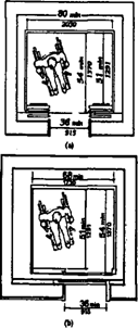
Fig. 23 (a) Panel Detail
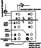
(b) Tactile,
Braille, and Visual Control Indicators. All control buttons shall be designated
by Braille and by raised standard alphabet characters for letters, Arabic
characters for numerals, or standard symbols as shown in Fig. 23(a), and as
required in
Fig. 20
Hoistway and Elevator Entrances
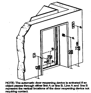
ASMEA17.1-1990. Raised and Braille characters and
symbols shall comply with 120-3-20-.41. The call button for the main
entry floor shall be designated bv a raised star at the left of the
floor designation (see Fig. 23(a)). All raised designations for
control buttons shall be placed immediately to the left of the button to which
they apply. Applied plates, permanently attached, are an acceptable means to
provide raised control designations. Floor buttons shall be provided with
visual indicators to show when each call is registered. The visual indicators
shall be extinguished when each call is answered.
(c) Height. All
floor buttons shall be no higher than 54 inches (1370 mm) above the
finish floor for side approach and 48 inches (1220 mm) for front
approach. Emergency controls, including the emergency alarm and emergency stop,
shall be grouped at the bottom of the panel and shall have their center lines
no less than 35 inches (890 mm) above the finish floor (see Fig. 23(a) and
(b)).
Page 53
(d) Location.
Controls shall be located on a front wall if the cars have center opening
doors, and at the side wall or at the front wall next to the door if cars have
side opening doors (see Fig. 23(c) and (d)).
Fig. 23
(c)
Alternate Locations of Panel with Center Opening
Door
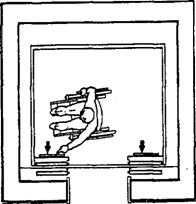
(d)
Alternate locations of Panel with Side Opening Door
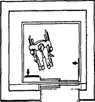
Note: Industry-wide standardization of
elevator control panel design would make all elevators significantly more
convenient for use by people with severe visual impairments. In many cases, it
will be possible to locate the highest control on elevator panels within 4
8
inches (1220 mm) from the floor.
Fig. 23 (b) Car Control Height
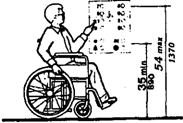
(13) Car Position Indicators. In
elevator cars, a visual car position indicator shall be provided above the car
control panel or over the door to show the position of the elevator in the
hoist way. As the car passes or stops at a floor served by the elevators, the
corresponding numerals shall illuminate, and an audible signal shall sound.
Numerals shall be a minimum of 1/2 inch (13 mm) high. The audible
signal shall be no less than 20 decibels with a frequency no higher
than 1500 Hz. An automatic verbal announcement of the floor number at which
a car stops or which a car passes may be substituted for the audible signal.
Note: A special button may be provided that
would activate the audible signal within the given elevator only for the
desired trip, rather than maintaining the audible signal in constant operation.
(14) Emergency Communications. If
provided, emergency two-way communication systems between the elevator and a
point outside the hoist way shall comply with ASMEA17.1 -1990. The highest
operable part of a two-way communication system shall be a maximum of
48 inches (1220 mm) from the floor of the car. It
shall be identified by a raised symbol and lettering complying with
120-3-20-.41 and located adjacent to the device. If the system uses a handset
then the length of the cord from the panel to the handset shall be at least 29
inches (735 mm). If the system is located in a closed compartment, the
compartment door hardware shall conform to rule rule 120-3-20-.38, Controls and
Operating Mechanisms. The emergency intercommunication system shall not require
voice communication.
Page 54
Note:
A
device that requires no handset is easier to use by people who have difficulty
reaching- Also, small handles on handset compartment doors are not usable by
people who have difficulty grasping.
Ideally, emergency two-way communication systems should provide
both voice and visual display intercommunication so that persons with hearing
impairments and persons with vision impairments can receive information
regarding the status of a rescue. A voice
intercommunication system cannot be the only means of
communication because it is not accessible to people with speech and hearing
impairments. While a voice intercommunication system is not required, at a
minimum, the system should provide both an audio and visual indication that a
rescue is on the way.
120-3-20-.22 Platform Lifts
(Wheelchair Lifts)
(1) Location.
Platform
lifts (wheelchair lifts) permitted by rule 120-3-20-.03 shall comply with the
requirements of rule 120-3-20-.22.
(2) Other Requirements. If
platform lifts (wheelchair lifts) are used, they shall comply with rules
120-3-20-13(4), 120-3-20-. 16(5), 120-3-20-.38(7), and ASME A17.1 Safety Code
for Elevators and Escalators, Section XX, 1990.
Note:
Inclined
stairway chair lifts, and inclined and vertical platform lifts (wheelchair
lifts) are available for short-distance, vertical transportation of people with
disabilities. Care should be taken in selecting lifts as some lifts are not
equally suitable for use by both wheelchair users and
semi-ambulatory individuals.
(3) Entrance. If
platform lifts are used then they shall facilitate unassisted entry, operation,
and exit from the lift in compliance with rule 120-3-20-.22(2).
Fig. 23 (a) Panel Detail
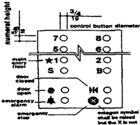
Fig. 43(a)
Proportions International Symbol of Accessibility
Page 55
120-3-20-.23 Windows
(1) General. Windows
intended to be operated by occupants in accessible spaces shall comply with
rule 120-3-20-.23.
(2) Window Hardware. Windows
requiring pushing, pulling, or lifting to open (for example, double-hung,
sliding, or casement and awning units without cranks) shall require no more
than 5 lbf (22.2 N) to open or close. Locks, cranks, and other
window hardware should comply with rule 120-3-20-.38.
120-3-20-.24 Doors
(1) General. Doors
required to be accessible by rule 120-3-20-.03 shall comply with the
requirements of rule 120-3-20-.24.
(2) Revolving Doors and Turnstiles. Revolving
doors or turnstiles shall not be the only means of passage at an accessible
entrance or along an accessible route. An accessible gate or door shall be
provided adjacent to the turnstile
or revolving door and shall be so designed as to
facilitate the same use pattern.
(3) Gates. Gates,
including ticket gates, shall meet all applicable specifications of rule
120-3-20-.23.
(4) Double-Leaf Doorways. If doorways have
two independently operated door leaves, then at least one leaf shall meet the
specifications in rule 120-3-20-.24(5) and rule 120-3-20-.24(6). That leaf
shall be an active leaf.
(5) Clear Width. Doorways
shall have a minimum clear opening of 32 inches (815 mm) with the
door open 90 degrees, measured between the face of the door and the opposite
stop (see Fig. 24(a), (b), (c), and (d)). Openings more than 24 inches (610 mm)
in depth shall comply with rule 120-3-20-.13(l) and rule 120-3-20-.14(3) (see
Fig. 24(e)).
EXCEPTION: Doors
not requiring full user passage, such as shallow closets, may have
the clear opening reduced to 20 inches (510 mm) minimum.
(6) Maneuvering Clearances at Doors. Minimum
maneuvering clearances at doors that are not automatic or power-assisted
shall be as shown in Fig. 25. The floor or ground area within the required
clearances shall be level and clear. NOTE: The exception for entry doors to
acute care hospital bedroom doors has been deleted because increasing the size
of the door does not change its dynamics and the State of Georgia requires all
rooms to be accessible.
Fig. 24
Clear Doorway Width end Depth
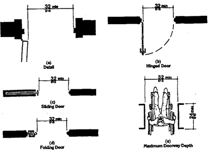
Page 56
Fig.25 (a) Front Approaches — Swinging Doors
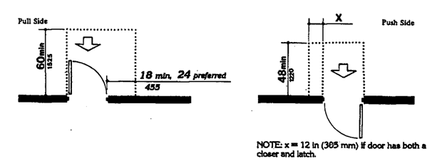
Fig. 25 (b)
Hinge Side Approaches — Swinging Doors
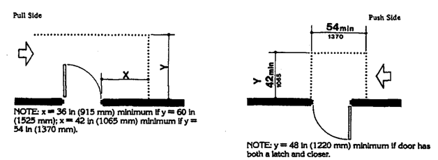
Fig. 25 (c)
Latch Side
Approaches — Swinging Doors
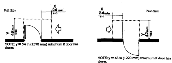
NOTE: Alt floors in alcoves shall comply with the
clearances for front approaches.
Page 57
Fig. 25
(d)
Front
Approach — Sliding Doors and Folding Doors
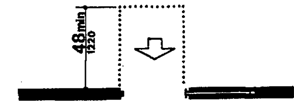
(e)
Slide
Side Approach — Sliding Doors and Folding Doors
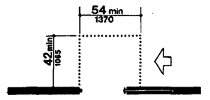
(f)
Latch Side Approach — Sliding Doors and Folding Doors
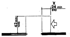
NOTE: All doors
in alcoves shall comply with the clearances for front approaches.
Fig. 26 Two Hinged Doors in Series
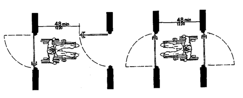
(7) Two
Doors in Series. The minimum space between two hinged or
pivoted doors in series shall be 48 inches (1220 mm) plus the
width of any door swinging into the space. Doors in series shall swing either
in the same direction or away from the space between the doors (see Fig. 26).
Page 58
(8) Thresholds at Doorways. Thresholds
at doorways shall not exceed 3/4 inches (19 mm) in height for exterior
sliding doors or 1/2 inches (13 mm) for other types of doors.
Raised thresholds and floor level changes at accessible doorways shall be
beveled with a slope no greater than 1:2 (see rule 120-3-20-.16(2)).
Note:
Thresholds
and surface height changes in doorways are particularly inconvenient for
wheelchair users who also have low stamina or restrictions in arm movement
because complex maneuvering is required to get over the level change while
operating the door.
(9) Door Hardware. Handles,
pulls, latches, locks, and other operating devices on accessible doors shall have
a shape that is easy to grasp with one hand and does not require tight
grasping, tight pinching, or twisting of the wrist to operate. Lever-operated
mechanisms, push-type mechanisms, and U-shaped handles are acceptable
designs. When sliding doors are fully open, operating hardware shall be exposed
and usable from both sides. Hardware required for accessible door passage shall
be mounted no higher than 48 inches (1220 mm) above finished floor.
Note:
Some
disabled persons must push against a door with their chair or walker to open
it. Applied kick plates on doors with closer can reduce required maintenance by
withstanding abuse from wheelchairs and canes. To be effective, they should
cover the door width, less
approximately 2 inches (51 mm) , up to a height of 16 inches
{405 mm) from its bottom edge and be centered across the width of the door.
(10) Door Closer.
If a door has a closer, then the sweep period of the closer shall be adjusted
so that from an open position of 70 degrees, the door will take at least 3
seconds to move to a point 3 inches (75 mm) from the latch, measured to the
leading edge of the door.
Note:
Closer
with delayed action features give a individual more time to maneuver through
doorways. They are particularly useful on frequently used interior doors such
as entrances to toilet rooms.
(11) Door Opening Force. The
maximum force for pushing or pulling open a door shall be as follows:
(a) Fire doors shall
have the minimum opening force allowable by the National Fire Protection
Association, NFPA 80 Fire Doors and Windows.
(b) Other doors:
(1) Exterior hinged doors: 8.5 lbs.
(37.9N)
(2) Interior hinged doors: 5 lbfs
(22.2N)
(3) Sliding / folding doors: 5 lbfs
(22.2N)
These forces do not apply to the force required to
retract latch bolts or disengage other devices that may hold the door a closed
position.
Page 59
Note:
Although
most people with disabilities can exert at least 5
lbf
(22.2N), both pushing and pulling from a stationary position, a few people with
severe disabilities cannot exert 3 lbf (13.13N). Although some people cannot manage
the allowable forces in this guideline and many others have difficulty, door
closer must have certain minimum closing forces to close doors satisfactorily.
Forces for
pushing or pulling doors open are measured with a push-pull
scale under the following conditions:
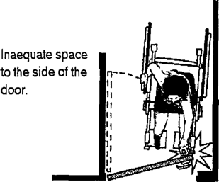
(1) Hinged doors: Force applied perpendicular to the door
at the door opener or 30 inches (760 mm) from the hinged side, whichever is
farther from the hinge.
(2) Sliding or
folding doors: Force applied parallel to the door at the door pull
or latch.
(3) Application
of force: Apply force gradually so that the applied force does not exceed
the resistance of the door. In high-rise buildings, air-pressure differentials
may require a modification of this
specification in order to meet the functional intent.
(12) Automatic Doors and Power-Assisted Doors. If
an automatic door is used, then it shall
Maneuvering Clearances at Doors
comply with ANSI/BHMA A156.10-1985. Slowly
opening, low-powered, automatic doors shall comply with ANSI A156.19-1984. Such
doors shall not open to back check faster than 3 seconds and shall require no
more than 15 lbf (66.6N) to stop door movement. If a power-assisted door
is used, its door-opening force shall comply with rule 120-3-20-.24(l 1) and
its closing shall conform to the requirements in ANSI A156.19-1984.
Note:
Sliding
automatic doors do not need guard rails and are more convenient for wheelchair
users and visually impaired people to use. If slowly opening automatic doors
can be reactivated before their closing cycle is completed, they will be more
convenient in busy doorways.
Page 60
120-3-20-.25 Entrances
(1) Minimum Number. Entrances
required to be accessible by rule 120-3-20-.03 shall be part of an accessible
route complying with rule 120-3-20-.14. Such entrances shall be connected
bv an accessible route to public transportation stops, to accessible
parking and passenger loading zones. and to public streets or sidewalks
if available (see rule 120-3-20-.14.(2)(1)). They
shall also be connected by an accessible route to all accessible spaces or
elements within the building or facility.
(2) Service Entrances. A service entrance
shall not be the sole accessible entrance unless it is the only entrance to a
building or facility (for example, in a factory or garage).
120-3-20-.26 Drinking
Fountains and Water Coolers
(1) Minimum Number. Drinking
fountains or water coolers required to be accessible by rule 120-3-20-.03 shall
comply with rule 120-3-20-.26.
(2) Spout Height. Spouts shall be no higher
than 36 inches (915 mm), measured from the floor or ground surfaces to
the spout outlet (see Fig. 27(a)).
Note: Two drinking fountains, mounted
side by side or on a single post, are usable by people with disabilities and people
who find it difficult to bend over.
(3) Spout Location. The spouts of drinking
fountains and water coolers shall be at the front of the unit and shall direct
the water flow in a trajectory that is parallel or nearly parallel to the
front of the unit. The spout shall provide a flow of
water at least 4 inches (100 mm) high so as to allow the insertion of a cup or
glass under the flow of water. On an accessible drinking fountain with a round
or oval bowl, the spout must be positioned so the flow of water is within 3
inches (75 mm) of the front edge of the fountain.
Fig. 27 (a)
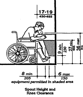
Fig.27 (b) Clear Floor Space
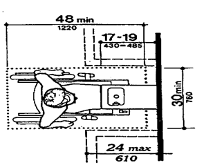
Page 61
(4) Controls. Controls shall comply with rule
120-3-20-.38(4). Unit controls shall be front mounted or side mounted near the
front edge.
(5) Clearances.(a) Wall
mounted and post mounted cantilevered units shall have a clear knee space
between the bottom of the apron and the floor or ground at least 27 inches (685
mm) high, 30 inches (760 mm) wide, and 17 inches to 19 inches (430 mm to 485
mm) deep (see Fig. 27(a) and (b)). Such units shall also have a minimum clear
floor space 30 inches by 48 inches (760 mm by 1220 mm) to allow a person in a
wheelchair to approach the unit facing forward.
(b) Free standing or
built-in units not having a clear space under them shall have a clear floor
space at least 30 inches by 48 inches (760 mm by 1220 mm) that allows a person
in a wheelchair to make a parallel approach to the unit (see Fig. 27(c) and
(d)). This clear floor space shall comply with 120-3-20-.13(4).
Fig. 27 (a)
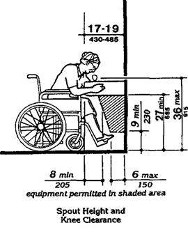
Fig.
27
Drinking
Fountains and Water Coolers
Free-Standing Fountain or Cooler
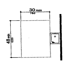
Built-in Fountain or Cooler
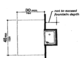
Page 62
120-3-20-.27 Water Closets
(1) General. Accessible
water closets shall comply with rule 120-3-20-.27.
(2) Clear Floor Space. Clear floor space for
water closets not in stalls
shall
comply with Fig. 28. Clear floor space may be arranged to allow either a left-handed
or right-handed approach.
Seats shall not be sprung to
return to a lifted position.
Fig.
28
Clear
Floor Space at Water Closets
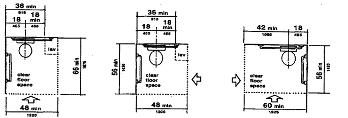
Fig. 29 Grab Bars at
Water Closets
(a) Back
Wall
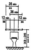
(b) Side
Wall
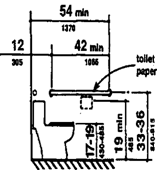
Note: Height preferences for toilet seats
vary considerably among disabled people. Higher seat heights may be an
advantage to some ambulatory disabled people, but are often a disadvantage for
wheelchair users and others. Toilet seats 18 inches (455 mm) high seem to be a
reasonable compromise. Thick seats and filler rings are available to adapt
standard fixtures to these requirements.
(4) Grab Bars. Grab bars for water closets
not located in stalls shall comply with rule 120-3-20-.37 and Fig. 29. The
grab bar behind the water closet shall be 36 inches (915 mm) minimum.
(3) Height. The
height of water closets shall be 17 inches to 19 inches (430 mm to 485 mm),
measured to the top of the toilet seat (see Fig. 29(b)).
Page 63
(a)
Diagonal Approach
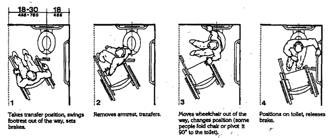
(b)
Side Approach
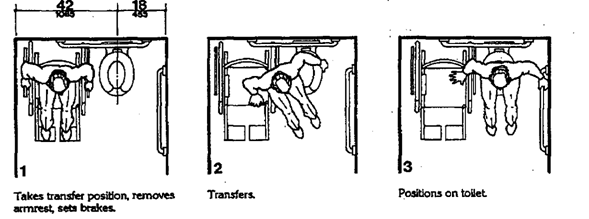
Note: Fig. A6(a) and (b) show the
diagonal and side approaches most commonly used to transfer from a wheelchair
to a water closet. Some wheelchair users can transfer from the front of the
toilet while others use a 90-degree approach. Most people who use the two
additional approaches can also use either the diagonal approach or the side
approach.
(5) Flush Controls. Flush
controls shall be hand operated or automatic and shall comply
with 120-3-20-.38(4). Controls for flush valves shall be mounted on the wide
side of toilet areas no more than 44 inches (1120 mm) above the floor.
Fig. A6
Wheelchair Transfers
Page 64
Note: Flush valves and related plumbing
can be located behind walls or to the side of the toilet, or a toilet seat lid
can be provided if plumbing fittings are directly behind the toilet seat. Such
designs reduce the chance of injury and imbalance caused by leaning back against
the fittings. Flush controls for tank-type toilets have a standardized mounting
location on the left side of the tank (facing the tank) . Tanks can be obtained
by special order with controls mounted on the right side. If administrative
authorities require flush controls for flush valves to be located in a position
that conflicts with the location of the rear grab bar, then that bar may be
split or shifted toward the wide side of the toilet area.
Fig. 30
(a)
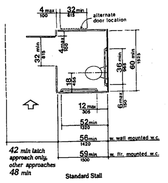
Fig. 30 (a-1) Standard
Stall (end of row)
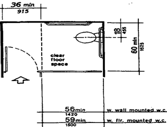
(6) Dispensers. Toilet paper dispensers shall
be installed within reach, as shown in Fig. 29(b). Dispensers that control
delivery, or that do not permit continuous paper flow, shall not be used.
120-3-20-.28 Toilet Stalls
(1) Location. Accessible
toilet stalls shall be on an accessible route and shall meet the requirements
of rule 120-3-20-.28.
(2) Water Closets. Water closets in
accessible stalls shall comply with rule 120-3-20-.27.
(3) Size and Arrangement. The
size and arrangement of the standard toilet stall shall comply with Fig.
30(a), Standard Stall, Standard toilet stalls with a minimum depth of 56
inches (1420 mm) (see Fig. 30(a)) shall have wall-mounted water closets. If the
depth of a standard toilet stall is increased at least 3 inches (75 mm), then a
floor - mounted water closet may be used. Arrangements shown for standard
toilet stalls may be reversed to allow either a left- or right - hand approach.
Additional stalls shall be provided in conformance with rule 102-3-20-.33(4).
Page 65
Fig. 30 (b) Alternate Stalls
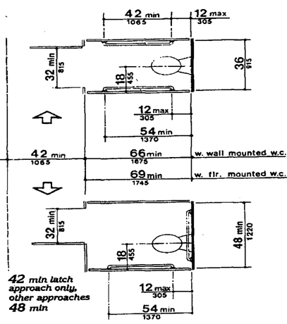
EXCEPTION: In instances of alteration
work
where provision of a standard stall
(Fig. 30(a)) is technically infeasible or where plumbing code requirements
prevent combining existing stalls to provide space, either alternate stall
(Fig. 30(b)) may be provided in lieu of the standard stall.
Note: This section requires use of the
60 inches (1525 mm) standard stall (Figure 30(a)) and permits the 36 inches
(915 mm) or 48 inches (1220 mm) wide alternate stall (Figure 30(b)) only in
alterations where provision of the standard stall is technically infeasible or
where local plumbing codes prohibit reduction in the number of fixtures. A
standard stall provides a clear space on one side of the water closet to enable
persons who use wheelchairs to perform a side or diagonal transfer from the
wheelchair to the water closet. However, some
persons with disabilities who use mobility aids such as walkers,
canes or crutches are better able to use the two parallel grab bars in the 36
inches (915 mm) wide alternate stall to achieve a standing position.
In large toilet rooms, where six or more toilet stalls are
provided, it is therefore required that a 36 inches (915 mm) wide stall with
parallel grab bars be provided in addition to the standard stall required in
new construction. The 36 inches (915 mm) width is necessary to achieve proper
use of the grab bars; wider stalls would position the grab bars too far apart
to be easily used and narrower stalls would position the grab bars too close to
the water closet. Since the stall is
primarily intended for use by persons using canes, crutches and
walkers, rather than wheelchairs, the length of the stall could be
conventional. The door, however, must swing outward to ensure a usable space
for people who use crutches or walkers.
Page 66
(4) Toe Clearances. In standard stalls, the
front partition and at least one side partition shall provide a toe clearance
of at least 9 inches (230 mm) above the floor. If the depth of the stall is
greater than 60 inches (1525 mm), then the toe clearance is not required.
(5) Doors.
Toilet
stall doors, including door hardware, shall comply with rule 120-3-20-.24. If
toilet stall approach is from the latch side of the stall door, clearance
between the door side of the stall and any obstruction may be reduced to a
minimum of 42 inches (1065 mm) (Fig. 30).
Note: To make it easier for wheelchair
users to close toilet stall doors, doors can be provided with closer, spring
hinges, or a pull bar mounted on the inside surface of the door near the hinge
side.
Fig. 30 (c)
Rear Wall of Standard Stall
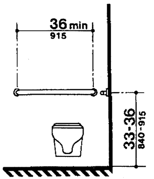
(6) Grab Bars. Grab
bars complying with the length and positioning shown in Fig. 30(a), (b), (c),
and (d) shall be provided. Grab bars may be mounted with any desired method as
long as they have a gripping surface at the locations shown and do not obstruct
the required clear floor area. Grab bars shall comply with rule 120-3-20-.37.
Fig. 30 (d)
Side Walls
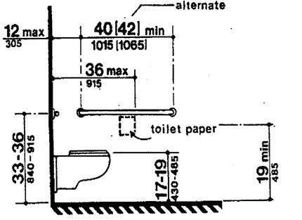
Page 67
120-3-20-.29 Urinals
(1) General. Any toilet or bathing room provided
with urinals must have at least one that complies with rule
120-3-20-.29.
(2) Height. Urinals
shall be stall-type or wall-hung with an elongated rim at a maximum of 17 inches
(430 mm) above the finish floor and extend at least 14 inches from
the back wall to the rim's front edge.
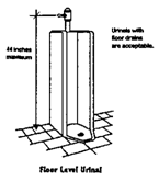
(3) Clear Floor Space.
A clear floor space 30 inches by 48 inches (760 mm
by 1220 mm) shall be provided in front of urinals to allow forward approach.
This
clear space shall adjoin or overlap an accessible
route and shall comply with rule 120-3-20-.13. Urinal shields that do not
extend beyond the front edge of the urinal rim may be provided with 29 inch
(735 mm) clearance between them.
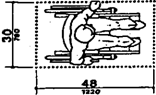

Fig. 31 Lavatory Clearances
(4) Flush Controls. Flush controls shall be
hand operated or automatic, and shall comply with rule 120-3-20-.38(4), and
shall be mounted no more than 44 inch (1120 mm) above the finish floor.
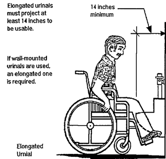
120-3-20-.30 Lavatories and
Mirrors
(1) General. The
requirements of rule 120-3-20-.30 shall apply to lavatory fixtures, vanities,
and built-in lavatories.
(2) Height and Clearances. Lavatories shall
be mounted with the rim or counter surface no higher than 34 inches (865 mm)
above the finish floor. Provide a clearance of at least 29 inches (735 mm)
above the finish floor to the bottom of the apron. Knee and toe clearance shall
comply with Fig. 31.
Page 68
(3) Clear Floor Space. A
clear floor space 30 inches by 48 inches (760 mm by 1220 mm) complying with
rule 120-3-20-.13 shall be provided in front of a lavatory to allow forward
approach. Such clear floor space shall adjoin or
overlap an accessible route and shall extend a
maximum of 19 inches (485 mm) underneath the lavatory (see Fig. 32).
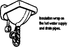
(4) Exposed Pipes and Surfaces. Hot water and
drain pipes under lavatories shall be insulated or otherwise configured to
protect against contact. There shall be no sharp or abrasive surfaces under
lavatories.
(5) Faucets.
Faucets
shall
comply with rule 120-3-20-.38(4). Lever -operated,
push-type, and electronically controlled mechanisms are examples of acceptable
designs. If self-closing valves are used the faucet shall remain open for at
least 10 seconds.
(6) Mirrors. Mirrors
shall be mounted with the bottom edge of the reflecting surface no higher than
40 inches (1015 mm) above the finish floor (see Fig. 31).
Note: If mirrors are to be used by both
ambulatory people and wheelchair users, then they must be at least 7 4 inches
(1880 mm) high at their topmost edge. A single full length mirror can
accommodate all people, including children.
Fig. 32
Clear Floor Space at Lavatories
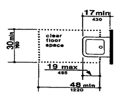
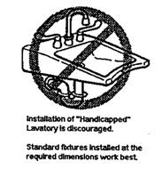
Standard sink and lavatories are
recommended.
Fig. 31 Lavatory Clearances
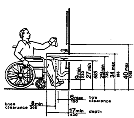
Page 69
120-3-20-.31 Bathtubs
(1) General. Accessible
bathtubs shall comply with rule 120-3-20-.31.
(2) Floor Space. Clear
floor space in front of bathtubs shall be as shown in Fig. 33.
(3) Seat. An
in-tub seat or a seat at the head end of the tub shall be provided as shown in
Fig. 33 and 34. The structural strength of seats and their attachments shall
comply with rule 120-3-20-37(3). Seats shall be mounted securely and shall not
slip during use.
(4) Grab Bars. Grab bars complying with rule
120-3-20-.37 shall be provided as shown in Fig. 33 and 34.
(5) Controls. Faucets
and other controls complying with rule 120-3-20-38(4) shall be located as shown
in Fig. 34.
(6) Shower Unit. A
shower spray unit with a hose at least 60 inches (1525 mm) long that can
be used both as a fixed shower head and as a hand-held shower shall be
provided.
(7) Bathtub Enclosures. If
provided, enclosures for bathtubs shall not obstruct controls or transfer from
wheelchairs onto bathtub seats or into tubs. Enclosures on bathtubs shall not
have tracks mounted on their rims.
Fig. 33
Clear Floor Space at Bathtubs
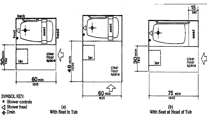
Page 70
Fig. 34
Grab
Bars at Bathtubs
(a)
With Seat in Tub
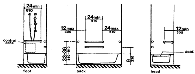
(b)
With Seat at Head of Tub
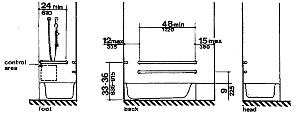
120-3-20-.32 Shower Stalls
(1) General. Accessible
shower stalls shall comply with rule 120-3-20-.32.
Note: Shower stalls that are 36 inches by
36 inches (915 mm by 915 mm) wide provide additional safety to people who have
difficulty maintaining balance because all grab bars and walls are within easy
reach. Seated people use the walls of 36 inches by 36 inches (915 mm by 915 mm)
showers for back support. Shower stalls that are 60 inches (1525 mm) wide and
have no curb may increase usability. of a bathroom by wheelchair users because
the shower area provides additional maneuvering space.
Page 71
(2) Size and Clearances. Except
as specified in rule 120-3-20-.51(2), shower stall size and clear floor space
shall comply with Fig. 35(a) or (b). The shower stall in Fig. 35(a) shall be 36
inches by 36 inches (915 mm by 915 mm). Shower stalls required by rule
120-3-20-.51(2) shall comply with Fig. 57(a) or (b). The shower stall in Fig.
35(b) will fit into the space required for a
bathtub.
Fig. 35
(a)
36-in by 36-ln (915-mm-by-915-mm) Stall
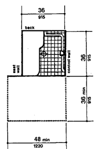
Fig. 57(b)
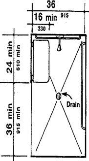
Fig- 57(a)
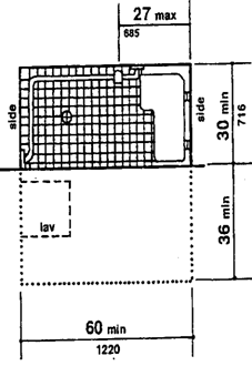
Fig. 35
(b)
30-In by 60-in (760-mm by 1525-mm) Stall
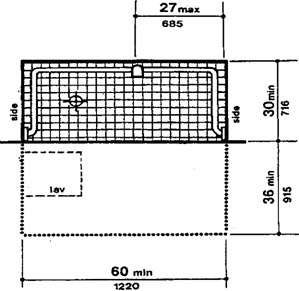
(3) Seat. A
seat shall be provided in shower stalls 36 inches by 36 inches (915 mm by 915
mm) and shall be as shown in Fig. 36. The seat shall be mounted 17 inches to 19
inches (430 mm to 485 mm) from the bathroom floor and shall extend the full
depth of the stall. In a 36 inches by 36 inches (915 mm by 915 mm) shower
stall, the seat shall be on the wall opposite the controls. Where a fixed seat
is provided in a 30 inches by 60 inches minimum (760 mm by 1525 mm) shower
stall, it shall be a folding type and shall be mounted on the wall adjacent to
the controls as shown in Fig. 57. The structural strength of seats and their
attachments shall comply with rule 120-3-20-.37(3).
Fig. 36
Shower Seat Design
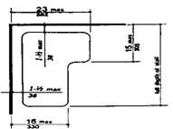
Page 72
Fig. 37
Crab Bars at Shower Stalls
(a)
36-in by 36-in (915-mm by 915-mm) Stall
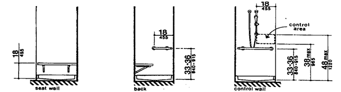
(b)
30-in by 60-in (760-mm by 1525-mm) Stall
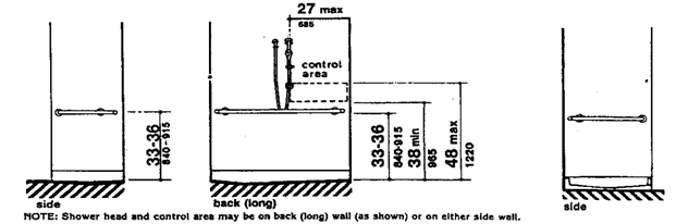
(4) Grab Bars. Grab bars complying with rule
120-3-20-.37 shall be provided as shown in Fig. 37.
(5) Controls. Faucets
and other controls complying with rule 120-3-20-38(4) shall be located as shown
in Fig. 37. In shower stalls 36 inches by 36 inches (915 mm by 915 mm),
all controls, faucets, and the shower unit shall be mounted on the side wall opposite
the seat.
(6) Shower Unit. A
shower spray unit with a hose at least 60 inches (1525 mm) long that can
be used both as a fixed shower head and as a hand-held shower shall be
provided.
EXCEPTION: In unmonitored facilities
where vandalism is a consideration, a fixed shower head mounted at 48 inches
(1220 mm) above the shower floor may be used in lieu of a hand-held showerhead.
(7) Curbs. If provided, curbs in shower
stalls 36 inches by 36 inches (915 mm by 915 mm) shall be no higher than 1/2
inch (13 mm). Shower stalls that are 30 inches by 60 inches (760 mm
by 1525 mm) minimum shall not have curbs.
(8) Shower Enclosures. If provided,
enclosures for shower stalls shall not obstruct controls or obstruct transfer
from wheelchairs onto shower seats.
Page 73
120-3-20-.33 Toilet Rooms
(1) Minimum Number. Toilet
facilities required to be accessible by rule 120-3-20-.03 shall comply with
rule 120-3-20-.33. Accessible toilet rooms shall be on an accessible route.
(2) Doors. All
doors to accessible toilet rooms shall comply with rule 120-3-20-.24. Doors
shall not swing into the clear floor space required for any fixture.
(3) Clear Floor Space. The
accessible fixtures and controls required in rules 120-3-20-33(4),
120-3-20-.33(5), 120-3-20-.33(6), and 120-3-20-33(7) shall be on an accessible
route. An unobstructed turning space complying with rule
120-3-20-.13(3) shall be provided within an accessible
toilet room. The clear floor space at fixtures and controls, the accessible
route, and the turning space may overlap.
Note: In many small facilities,
single-user rest rooms may be the only facilities provided for all building
users. In addition, the rules allow the use of "unisex" or
"family" accessible toilet rooms in alterations when technical in-feasibility
can be demonstrated.
FIG. 3
(a)
60-In (1525-mm)-Diameter Space
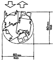
Fig. 3
(b)
T-Shaped Space for 180' Turns
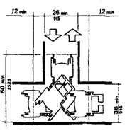
Minimum Accessible Toilet Room using the T-Turn.
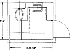
Minimum Accessible Toilet Room using 5'
turning
radius
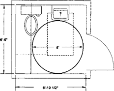
Experience has shown that the provision of accessible
"unisex" or single-user rest rooms is a reasonable way to provide
access for wheelchair users and any attendants, especially when
attendants are of the opposite sex. Since these facilities have
proven so useful, it is often considered advantageous to install a
"unisex" toilet room in new facilities in addition to making the
multi-stall rest rooms accessible, especially in shopping malls, large auditoriums,
and convention
centers.
Page 74
Figure 28 (section rule 120-3-20-.27) provides
minimum clear floor space dimensions for toilets in accessible
"unisex" toilet rooms. The dotted lines designate the minimum clear
floor space, depending on the direction of approach, required for wheelchair
users to transfer onto the water closet. The dimensions of 48 inches (1220 mm)
and 60 inches (1525 mm), respectively, correspond to the space required for the
two common transfer approaches utilized by wheelchair users (see Fig. A6) . It is
important to keep in mind that the placement of the lavatory to the immediate
side of the water closet will preclude the side approach transfer illustrated
in Figure A6(b). To accommodate the side transfer, the space adjacent to the
water closet must remain clear of obstruction for 42 inches (1065 mm) from the
centerline of the toilet {Figure 28) and the lavatory must not be located
within this clear space. A turning circle or T-turn, the clear floor space at
the lavatory, and maneuvering space at the door must be considered when
determining the possible wall locations. A privacy latch or other accessible
means of ensuring privacy during use should be provided at the door.
RECOMMENDATIONS:
1. In new construction, accessible single-user rest rooms may be
desirable in some situations because they can accommodate a wide variety of
building users. However, they cannot be used in lieu of making the multi-stall
toilet rooms accessible as required.
2. Where strict compliance to the rules for accessible toilet
facilities is technically infeasible in the alteration of existing facilities,
accessible "unisex" toilets are a reasonable alternative.
3. In designing accessible single-user rest rooms, the
provisions of adequate space to allow a side transfer will provide
accommodation to the largest number of wheelchair users.
(4) Water Closets. If
toilet stalls are provided, then at least one shall be a standard toilet stall
complying with rule 120-3-20-.28; where 6 or more stalls are provided, in
addition to the stall complying with rule 120-3-20-.28(3), at least one stall
36 inches (915 mm) wide with an outward swinging, self-closing door and
parallel grab bars complying with Fig. 30(d) and rule 120-3-20-.37 shall be
provided. Water closets in such stalls shall comply with rule 120-3-20-.27. If
water closets are not in stalls, then at least one shall comply with rule
120-3-20-.27.
(5) Urinals.
If
urinals are provided, then at least one shall comply
with rule 120-3-20-.29.
(6) Lavatories and Mirrors. If
lavatories and mirrors are provided, then at least
one of each shall comply with rule 120-3-20-.30.
(7) Controls and Dispensers. If controls,
dispensers, receptacles, or other equipment are provided, then at least one of
each shall be on an accessible route and shall comply with rule 120-3-20-.38.
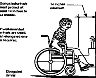
Page 75
Fig. A7
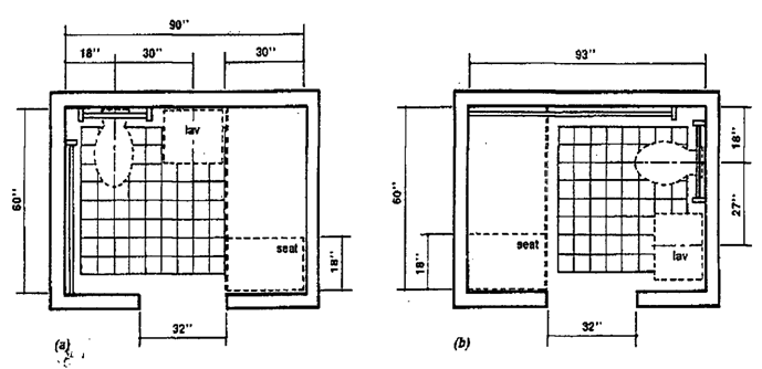
120-3-20-.34 Bathrooms,
Bathing Facilities, and Shower Rooms
(1) Minimum Number. Bathrooms,
bathing facilities, or shower rooms required to be accessible by rule
120-3-20-.4.1 shall comply with rule 120-3-20-.4.23 and shall be on an
accessible route.
(2) Doors. Doors
to accessible bathrooms shall comply with rule 120-3-20-.24. Doors shall not
swing into the floor space requiredfor any fixture.
(3) Clear Floor Space. The accessible
fixtures and controls required in rules 120-3-20-.34(4), 120-3-20-.34(5),
120-3-20-.34(6), 120-3-20-34(7), 120-3-20-.34(8), and 120-3-20-.34(9) shall be
on an accessible route. An unobstructed turning space complying
with rule 120-3-20-.13(3) shall be provided within an accessible bathroom. The
clear floor spaces at fixtures and controls, the accessible route, and the
turning space may overlap.
Note: Figure A7 shows two
possible configurations of a toilet room with a roll-in shower. The specific
shower shown is designed to fit exactly within the dimensions of a standard
bathtub. Since the shower does not have a lip, the floor space can be used for
required maneuvering space. This would permit a toilet room to be smaller than
would be permitted with a bathtub and still provide enough floor space to be
considered accessible. This design can
provide accessibility in facilities where space is at a premium
(i.e., hotels and medical care
facilities). The alternate roll-in shower (Fig. 57b) also
provides sufficient room for the "T-turn" and does not require
plumbing to be on more than one wall.
Page 76
(4) Water Closets. If
toilet stalls are provided, then at least one
shall be a standard toilet stall
complying with rule 120-3-20-.28; where 6 or more
stalls are provided, in addition to the stall complying with rule
120-3-20-.28(3), at least one stall 36 inches (915 mm) wide with an outward
swinging, self-closing door and parallel grab bars complying with Fig. 30(d)
and rule 120-3-20-.37 shall be provided. Water closets in such stalls shall
comply with rule 120-3-20-.27. If water closets are not in stalls, then at
least one shall comply with rule 120-3-20-.27.
Fig. 57(b)
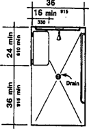
(5) Urinals.
If
urinals are provided, then at least one shall comply with rule
120-3-20-.29.
(6) Lavatories and Mirrors. If lavatories and
mirrors are provided, then at least one of each shall comply with rule
120-2-20-.30.
(7) Controls and Dispensers. If controls,
dispensers, receptacles, or other equipment are provided, then at least one of
each shall be on an accessible route and shall comply with rule 120-2-20-.38.
(8) Bathing and Shower Facilities. If tubs or
showers are provided, then at least one accessible tub that complies
with rule 120-2-20-.31 or at least one accessible shower that complies with
rule 120-
2-20-.32 shall be provided.
(9) Medicine Cabinets. If
medicine cabinets are provided, at least one shall be located with a
usable shelf no higher than 44 inches (1120 mm) above the floor space.
The floor space shall comply with rule 120-2-20-.13(4).
Note: Other alternatives for storing
medical and personal care items are very useful to disabled people. Shelves,
drawers, and floor-mounted cabinets can be provided within the reach ranges of
disabled people. Maximum reach height shall comply with
rule 120-2-20-.13, with a height of 48 inches (1220 mm)
preferred irrespective of approach allowed.
Fig. 30 (a)
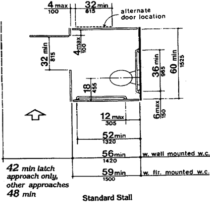
Page 77
120-3-20-.35 Sinks
(1) General. Sinks
required to be accessible by rule 120-3-20-.03 shall comply with rule
120-3-20-.35.
(2) Height. Sinks shall
be mounted with the counter or rim no higher than 34 inches (865
mm) above the finish floor.
Standard sink designs are recommended to
be used instead of the handicapped sink designs where possible. All required
clearance shall be complied with.
(3) Knee Clearance. Knee
clearance that is at least 27 inches (685 mm) high, 30 inches (760 mm) wide,
and 19 inches (485 mm) deep shall be provided underneath sinks.
(4) Depth. Each sink shall be a maximum
of 6-1/2 inches (165 mm) deep.
(5) Clear Floor Space. A
clear floor space at least 30 inches by 48 inches (760 mm by 1220 mm) complying
with rule 120-3-20-.13(4) shall be provided in front of a sink to allow forward
approach. The clear floor space shall be on an
Fig. 32
Clear Floor Space at Lavatories
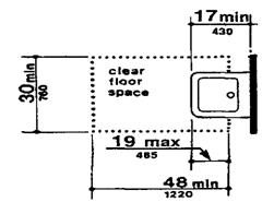
accessible route and shall extend a maximum of 19
inches (485 mm) underneath the sink (see Fig. 32).
(6) Exposed Pipes and Surfaces. Hot
water and drain pipes exposed under sinks shall be insulated or otherwise
configured so as to protect against contact. There shall be no sharp or
abrasive surfaces under sinks.
Fig. 31 Lavatory Clearances
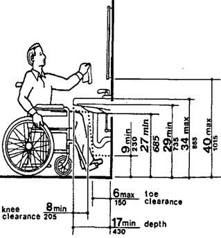
(7) Faucets. Faucets shall comply with rule
120-3-20-.38(4). Lever - operated, push-type, touch-type, or electronically controlled
mechanisms are acceptable designs.
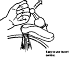
Page 78
Fig. 38 (a) Shelves
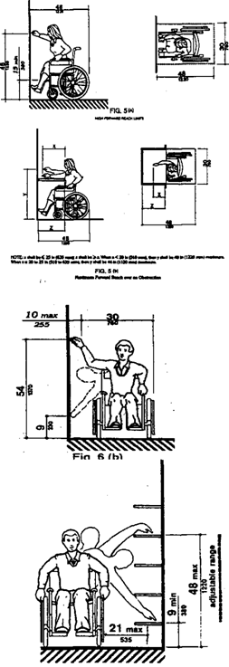
120-3-20-.36 Storage
(1) General. Fixed
storage facilities such as cabinets, shelves, closets, and drawers required to
be accessible by rule 120-3-20-.03 shall comply with rule 120-3-20-.36.
(2) Clear Floor Space. A clear floor space at
least 30 inches by 48 inches (760 mm by 1220 mm) complying with rule
120-3-20-.12(4) that allows either a forward or parallel approach by a person
using a wheelchair shall be provided at accessible storage facilities.
(3) Height. Accessible
storage spaces shall be within at least one of the reach ranges specified in
rule 120-3-20-.13(5) and rule 120-3-20-.13(6) (see Fig. 5 and Fig 6). Clothes
rod or shelves shall be a maximum of 54 inches (1370 mm) above the finish floor
for a side approach. Where the distance from the wheelchair to the clothes
rods or shelf exceeds 10 inches (255 mm) (as in closets
without accessible doors) the height and depth to the rod or shelf shall comply
with Fig. 38(a) and Fig. 38(b).
Fig. 38 (b) Closets
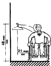
Fig. 6 (c) Side
Reach

(4) Hardware. Hardware for accessible storage
facilities shall comply with rule 120-3-20-.38(4). Touch latches and U-shaped
pulls are acceptable.
Page 79
120-3-20-.37 Handrails, Grab
Bars, and Tub and Shower Seats
(1) General. All handrails,
grab bars, and tub and shower seats required to be accessible by rules
120-3-20-.03,120-3-20-.19,120-3-20-.20,120-3-20-.27, 120-3-20-.28, 120-3-20-.31
or 120-3-20-.32 shall comply with rule 120-3-20-.37.
Fig. 39(a) Handrail
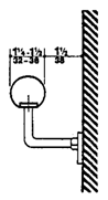
Note: Many disabled people rely heavily
upon grab bars and handrails to maintain balance and prevent serious falls.
Many people brace their forearms between supports and walls to give them more
leverage and stability in maintaining balance or for lifting. The grab bar
clearance of 1-1/2 inches
(38
mm) required in these rules is a safety clearance to prevent injuries resulting
from arms slipping through the openings. It also provides adequate gripping
room.
(2) Size and Spacing of Grab Bars and
Handrails. The diameter or width of the gripping
surfaces of a handrail or grab bar shall be 1-1/4 inches to 1-1/2 inches (32
mm to 38 mm), or the shape shall provide an equivalent gripping surface. If
handrails or grab bars are mounted adjacent to a wall, the space between the
wall and the grab bar shall be 1-1/2 inches (38 mm) (see Fig. 39(a),
(b), and
Handrails may be located in a recess if the recess
is a maximum of 3 inches (75 mm) deep and extends at least 18 inches (455 mm)
above the top of the rail (see Fig. 39(c)).
Note: This specification allows for
alternate shapes of handrails as long as they allow an opposing grip similar to
that provided by a circular section of 1-1/4 inches to 1-1/2 inches (32 mm to
38 mm).
(3) Structural Strength.
The structural strength of grab bars, tub and shower
seats, fasteners, and mounting devices shall meet the following specification:
(a) Bending stress
in a grab bar or seat induced by the maximum bending moment from the
application of 250 Ibf (1112 N) shall be less than the allowable stress
for the material of the grab bar or seat.
Fig. 39(c)
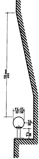
(b) Shear stress
induced in a grab bar or seat by the application of 250 lbf (1112 N)
shall be less than the allowable shear stress for the material of the grab bar
or seat. If the connection between the grab bar or seat and its mounting
bracket or other support is considered to be fully restrained,
Fig. 39(b)
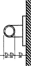
Page 80
then direct and torsional shear stresses shall be
totaled for the combined shear stress, which shall not exceed the allowable
shear stress.
(c) Shear force
induced in a fastener or mounting device from the application of 250 lbf (1112
N) shall be less than the allowable lateral load of either the fastener or
mounting device or the supporting structure, whichever is the smaller allowable
load. '
(d) Tensile force
induced in a fastener by a direct tension force of 250 lbf (1112 N) plus
the maximum moment from the application of 250 lbf (1112 N) shall be less than
the allowable withdrawal load between the fastener and
the supporting structure.
(e) Grab bars shall not rotate within their
fittings.
(4) Eliminating Hazards. A handrail or grab bar
and any wall or other surface adjacent to it shall be free of any sharp or
abrasive elements. Edges shall have a minimum radius of 1/8 inch (3.2
mm).
120-3-20-.38 Controls and
Operating Mechanisms
(1) General. Controls
and operating mechanisms required to be accessible by rule 120-3-20-.03 shall
comply with rule 120-3-20-.38.
Fig. 39(b)
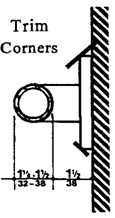
(2) Clear Floor Space. Clear
floor space complying with rule 120-3-20-.13(4) that allows a forward or a
parallel approach by a person using a wheelchair shall be provided at controls,
dispensers, receptacles, and other operable equipment.
(3) Height. The
highest operable part of controls, dispensers, receptacles, and other operable
equipment shall be placed within at least one of the reach ranges specified in
rule 120-3-20-.13(5) and rule 120-3-20-.13(6). Electrical and communications
system receptacles on walls shall be mounted no less than 15 inches (380
mm) above the floor.
FIG. 5 (a)
High Forward Reach Units
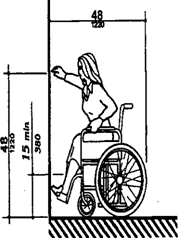
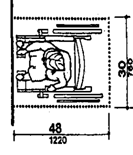
EXCEPTION: These requirements do not
apply where the use of special equipment dictates otherwise or where electrical
and communications systems receptacles are not normally intended for use by
building occupants.
Page 81
Fig. A8 Control Reach Limitations
Forward Reach Possible
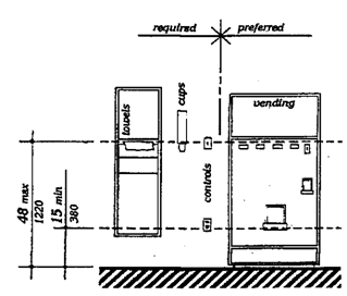
(b)
Side Reach Possible
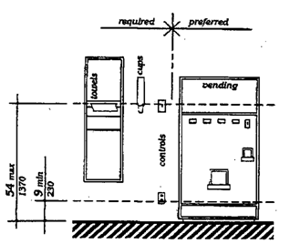
Note: Fig. A8
further
illustrates mandatory and advisory control mounting height provisions for
typical equipment. Electrical receptacles installed to serve individual
appliances and not intended for regular or frequent use by building occupants
are not required to be mounted within the specified reach ranges. Examples
would be receptacles installed specifically for wall-mounted clocks,
refrigerators, and microwave ovens.
Fig. 44(a) Side Reach Possible
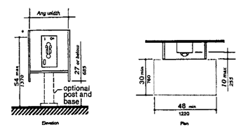
(4) Operation.
Controls and operating mechanisms shall be operable with one hand and
shall not require tight grasping, pinching, or twisting of the wrist.
The force required to activate controls shall be no greater than 5 lbf
(22.2 N).
Forward Reach Required Fig. 44(b)
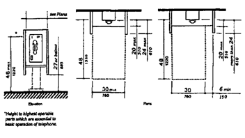
Page 82
120-3-20-.39 Alarms
(1) General. Alarm
systems required to be accessible by rule 120-3-.20-.03 shall comply with rule
120-3-.20-.39. At a minimum, visual signal appliances shall be provided
in buildings and facilities in each of the following areas: restrooms and
any other general usage areas (e.g.t class rooms, meeting rooms),
hallways, lobbies, and any other area for common use.
(2) Audible Alarms. If
provided, audible emergency alarms shall produce a sound that exceeds the
prevailing equivalent sound level in the room or space by at least 15 dbA or
exceeds any maximum sound level with a duration of 60 seconds by 5 dbA,
whichever is louder. Sound levels for alarm signals shall not exceed
120 dbA.
Note: Audible emergency signals must
have an intensity and frequency that can attract the attention of individuals
who have
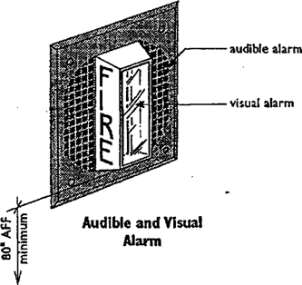
partial hearing loss. People more than 60 years of age generally
have difficulty perceiving frequencies higher than 10,000 Hz. An alarm signal
which has a periodic element to its signal, such as single stroke bells
(clang-pause-clang-pause), hi-low (up-down-up-down) and fast whoop
{on-off-on-off) are best. Avoid continuous or reverberating tones. Select a
signal which has a sound characterized by three or four clear tones without a
great deal of "noise" in between.
(3) Visual Alarms.
Visual alarm signal appliances shall be integrated into the building or
facility alarm system. If single station audible alarms are provided then
single station, visual alarm signals shall be provided. Visual alarm signals
shall have the following minimum photometric and location features:
(a) The lamp shall be a xenon strobe type or
equivalent.
(b) The color shall be clear or nominal white (i.e.,
unfiltered or clear filtered white light).
(c) The maximum pulse duration shall be two-tenths
of one second (0.2 sec) with a maximum duty cycle of 40 percent. The pulse
duration is defined as the time interval between initial and final points of 10
percent of maximum signal.
(d) The intensity shall be a minimum of 75 candela.
(e) The flash rate shall be a minimum of 1 Hz and a
maximum of 3 Hz.
Page 83
(f) The appliance shall be placed 80 inches (2030
mm) above the highest floor level within the space or 6
inches (152 mm) below the ceiling, whichever is lower.
(g) In general, no
place in any room or space required to have a visual signal appliance shall be
more than 50 feet (15 m) from the signal (in the horizontal plane). In
large rooms and spaces exceeding 100 feet (30 m) across, without obstructions 6
feet (2 m) above the finish floor, such as auditoriums, devices may be placed
around the perimeter, spaced a maximum 100 ft (30 m) apart, in lieu of
suspending appliances from the ceiling.
(h) No place in common corridors or hallways in
which visual alarm signaling appliances are required shall be more than 50 feet
(15 m) from the signal.
Note: The specifications in this section
do not preclude the use of zoned or coded alarm systems.
(4) Auxiliary Alarms. Units
and sleeping accommodations shall have a visual alarm connected to the building
emergency alarm system or shall have a standard 110-volt
electrical receptacle into which such an alarm can be connected and a means by
which a signal from the building emergency alarm system can trigger such an
auxiliary alarm. When visual alarms are in place the signal shall be visible in
all areas of the unit or room. Instructions for use of the auxiliary alarm or
receptacle shall be provided.
Note: Locating visual
emergency alarms in rooms where persons who are deaf may work or reside alone
can ensure that they will always be warned when an emergency alarm is
activated. To be effective, such devices must be located and oriented so that
they will spread signals and reflections throughout a space or raise the
overall light level sharply. However, visual alarms alone are not necessarily
the best means to alert sleepers. A study conducted by Underwriters Laboratory
(UL) concluded that a flashing light more than seven times brighter was
required (110 candela v. 15 candela, at the same distance) to awaken sleepers
as was needed to alert awake subjects in a normal daytime illuminated room.
For hotel and other rooms where people are likely to
be asleep, a signal activated vibrators placed between mattresses and box
springs or under pillows were found by UL to be much more effective in alerting
sleepers. Many readily available devices are sound - activated so that they
could respond to an alarm clock, clock radio, wake-up telephone call or room
smoke detector. Activation by a building alarm system can be accomplished
either by a separate circuit activating an auditory alarm which would, in turn,
trigger the vibrator or by a signal transmitted through the ordinary 110-volt
outlet. Transmission of signals through the power line is relatively simple and
is the basis of common, inexpensive remote light control systems sold in many
department and electronic stores for home use. So-called "wireless"
intercoms operate on the same principal.
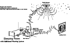
Page 84
120-3-20-.40 Detectable
Warnings
(1) General. Detectable warnings required by
rule 120-3-20-.03 and rule 120-3-20-.18 shall comply with rule 120-3-20-.40.
(2) Detectable Warnings on
Walking Surfaces.
Detectable warning textures on walking surfaces
shall consist of exposed aggregate concrete, cushioned surfaces made of rubber
or plastic, raised strips, or grooves. Texture shall contrast with
that of the surrounding surface. Raised strips or grooves shall comply with
Fig.40. Grooves may be used indoors only.
Grooves way
be used indoors only.
Note: The material used to provide
contrast should contrast by at least 70%. Contrast in percent is determined by:
Contrast = [(B1 - B2)/B1]
x 100
where B1 = light reflectance
value (LRV) of the lighter area and B2 = light reflectance value
(LRV) of the darker area.
Note that in any
application both white and black are never absolute; thus, B1 never
equals 100 and B2 is always greater than 0.
Fig. 40
Strips and Grooves used as Tactile
Warnings on Walking Surfaces
(a)
Plan of Tactile Warning Surface
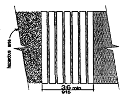
(b)
Sections of Tactile Warning Surfaces
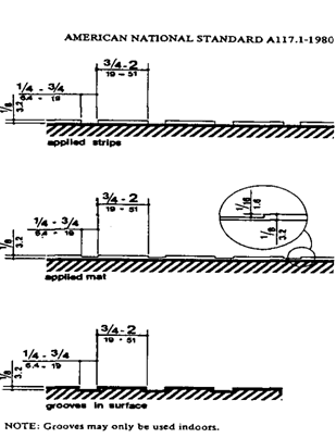
Page 85
(3) Tactile Warning on Doors to
Hazardous Areas. Doors that lead to areas that might
prove dangerous to a person with a vision disability. (For example, doors to
loading docks, platforms, boiler rooms, stages, and the like) shall be made
identifiable to the touch by a textured surface on the door
handle, knob, pull, or other operating hardware. The texture
surface made be made by knurling or roughening or by a material applied to the
contact surface.
Such texture surfaces shall not be
provided for emergency doors or any door other than those to hazardous
areas.
(4) Detectable Warning at Stairs.
All stairs,
except those in dwelling units, in enclosed stair towers, or set to side of the
path of travel shall have a detectable warning at the top of the each stair
run, at least 36 inches deep and as wide as the stairs. (See Fig. 41 and rule
120-3-20-.20(5))
Fig. 41 Tactile Warning at Stairs
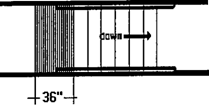
(5) Detectable Warning at Hazardous
Vehicular Areas. If a walk crosses or adjoins a
frequently used vehicular way, and if there are no curbs, railing, or other
elements detectable by a person who has a visual disability separating the
pedestrian and vehicular areas, the boundary between the areas shall be defined
by a continuous, detectable warning texture, which is 36 inches wide,
complying with rule 120-3-20-.20(5). (See Fig. 42)
(6) Detectable Warning at Reflecting
Pools.
The edges of reflecting pools shall be protected by
railing, walls, curbs, or detectable warning complying with rule
120-3-20-.20(5).
(7) Standardization. Textured surfaces for
detectable warnings shall be standard within a building, facility, site, or
complex of buildings.
(8) Outdoor Conditions. Outdoor
stairs and then-approaches shall be designed so that water will not accumulate
on walking surfaces.
(9) Detectable Warnings at Rail and
Train Stations. Detectable warnings shall consist of
raised truncated domes with a diameter of nominal 0.9 inches (23 mm), a height
of nominal 0.2 inches (5 mm) and a center-to-center spacing of nominal 2.35
inches (60 mm) and shall contrast visually with adjoining surfaces,
either
light-on-dark, or dark-on-light. The material
used to provide contrast shall be an integral part of the walking
surface. Detectable warnings used on interior surfaces shall differ
from adjoining walking surfaces in resiliency or sound-on-cane contact.
Fig. 42
Tactile Warning at Hazardous Vehicular Areas
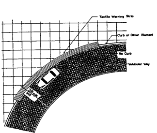
Page 86
120-3-20-.41 Signage
(1) General. Signage
required to be accessible by rule 120-3-20-.03 shall comply with the applicable
provisions of rule 120-3-20-.41.
Note: In building complexes where finding
locations independently on a routine basis may be a necessity (for example,
college campuses), tactile maps or prerecorded instructions can be very helpful
to visually impaired people. Several maps and
auditory instructions have been developed and tested for
specific applications. The type of map or instruction used must be based on the
information to be communicated, which depends highly on the type of buildings
or user.
Landmarks that can easily be distinguished by visually impaired
individuals are useful as orientation cues. Such cues include changes in
illumination level, bright colors, unique patterns, wall murals, location of
special equipment or other architectural features.
Many people with disabilities have limitations in movement of
their heads and reduced peripheral vision. Thus, signage positioned
perpendicular to the path of travel is easiest for them to notice. People can
generally distinguish signage within an angle of 30 degrees
to either side of the centerline of their faces without moving their heads.
(2) Character
Proportion. Letters and numbers on signs shall have a width-to-height ratio
between 3:5 and 1:1 and a stroke-width-to-height ratio between 1:5 and 1:10.
Note: The legibility of printed characters is a
function of the viewing distance, character height, the ratio of the stroke
width to the height of the character, the contrast of color between character
and background and print fonts. The size of characters must be based upon the
intended viewing distance. A severely
nearsighted person may have to be much closer to
recognize a character of a given size than a person with normal visual acuity.
(3) Character
Height. Characters and numbers on signs shall be sized according to the viewing
distance from which they are to be read. The minimum height is measured using
an uppercase X. Lowercase characters are permitted.
|
Height above Finish Floor
|
Minimum Character Height
|
|
Suspended or Projected Overhead in compliance with
rule 120-3-20-.15(2)
|
3 inches (75 mm) minimum
|
Page 87
(4) Raised
and Braille Characters and Pictorial Symbol Signs (Pictograms). Letters
and numerals shall be raised 1/32 inch, uppercase, sans serif or simple serif
type and shall be accompanied with Grade 2 Braille. Raised
characters shall be at least 5/8 inch (16 mm) high, but no higher than 2 inches
(50 mm). Pictograms shall be accompanied by the equivalent verbal description
placed directly below the pictogram. The border dimension of the pictogram
shall be 6 inches (152 mm) minimum in height.
Note: The standard dimensions
for literary Braille are as follows:
|
Dot diameter
|
.059 inch.
|
|
Inter-dot spacing
|
.090 inch.
|
|
Horizontal separation between cells
|
.241 inch.
|
|
Vertical separation between cells
|
.395 inch.
|
Raised borders around signs containing raised characters may
make them confusing to read unless the border is set far away from the
characters. Accessible signage with descriptive materials about public
buildings, monuments, and objects of cultural interest may not provide
sufficiently detailed and meaningful information.
Interpretive guides, audio tape devices, or other methods may be
more effective in presenting such information.
(5) Finish and Contrast. The
characters and background of signs shall be eggshell, matte, or other non glare
finish. Characters and symbols shall contrast with their background — either
light characters on a dark background or dark characters on a light background.
Note: An eggshell finish (11 to 19
degree gloss on 60 degree glossimeter) is recommended. Research indicates that
signs are more legible for persons with low vision when characters contrast
with their background by at least 70 percent. Contrast in percent shall be
determined by:
Contrast = [(B1
- B2)/B1] x 100
where B.,= light reflectance value (LRV)
of the lighter area and B2= light reflectance value (LRV) of the
darker area.
Note: in any application both
white and black are never absolute; thus, B1 never
equals 100 and B2 is greater
than 0.
The greatest readability is usually achieved through the use of
light-colored characters or symbols on a dark background.
Page 88
(6) Mounting Location and Height. Where
permanent identification is provided for rooms and spaces, signs shall be
installed on the wall adjacent to the latch side of the door. 'Where there is
no wall space to the latch side of the door, including at double leaf doors,
signs shall be placed on the nearest adjacent wall. Mounting height
shall be 60 inches (1525 mm) above the finish floor to the centerline of
the sign. Mounting location for such signage shall be so that a
person may approach within 3 inches (76 mm) of signage without encountering
protruding objects or standing within the swing of a door.
(7) Symbols of Accessibility.
(a) Facilities and
elements required to be identified as accessible by rule 120-3-20-.03 shall use
the international symbol of accessibility. The symbol shall be displayed as
shown in Fig. 43(a) and (b).
(b) Volume Control Telephones. Telephones required
to have a volume control by rule 120-3-20-.08(17)(b) shall be identified by a sign
containing a depiction of a telephone handset with radiating sound waves.
(c) Text Telephones.
Text telephones required by rule 120-3-20-.08 (17)(c) shall be identified by
the international TDD symbol (Fig 43(c)). In addition, if a facility has a
public text telephone, directional signage indicating the location of the
nearest text telephone shall be placed adjacent to all banks of telephones
which do not contain a text telephone. Such directional signage shall include
the international TDD symbol. If a facility has no banks of telephones, the
directional signage shall be provided at the entrance (e.g., in a building
directory).
(d) Assistive Listening Systems. In assembly areas
where permanently installed assistive listening systems are required by rule
120-3-20-.08(19)(b) availability of such systems shall be identified with
signage that includes the international symbol of access for hearing loss (Fig
43(d)).
Fig. 43(a) Proportions
International Symbol of Accessibility
Fig. 43(b)
Display Conditions International Symbol of Accessibility

Fig. 43(c)
International TDD Symbol

Fig. 43(d) International Symbol
of Access for Hearing Loss

Page 89
Note: Paragraph 4 of this section
requires signage indicating the availability of an Assistive Listening System. An
appropriate message should be displayed with the international symbol of access
for hearing loss since this symbol conveys general accessibility for people
with hearing loss. Some suggestions are:
INFRARED ASSISTIVE LISTENING SYSTEM AVAILABLE
----PLEASE ASK----
AUDIO LOOP IN USE TURN T-SWITCH FOR BETTER REARING
----OR ASK FOR HELP----
FM
ASSISTIVE LISTENING SYSTEM AVAILABLE ----PLEASE
ASK----
The symbol may be used to notify persons of the availability of
other
auxiliary aids and services such as: real time captioning,
captioned note taking, sign language interpreters, and oral interpreters.
(8) Illumination Levels. (Reserved).
Note: Illumination levels on the sign
surface shall be in the 100 to 300 lux range (10 to 30 foot candles) and shall
be uniform over the sign surface. Signs shall be located such that the
illumination level on the surface of the sign is not significantly exceeded by
the ambient light or visible bright lighting source behind or in front of the
sign.
120-3-20-.42 Telephones
(1) General. Public
telephones required to be accessible by rule 120-3-20-.03 shall comply with
rule 120-3-20-.42.
(2) Clear Floor or
Ground Space. A clear floor or ground space at least 30 inches by 48 inches
(760 mm by 1220 mm) that allows either a forward or parallel approach by a
person using a wheelchair shall be provided at telephones (see Fig.44). The
clear floor or ground space shall comply with rule 120-3-20-.13(4). Bases,
enclosures, and fixed seats shall not impede approaches to telephones by people
who use wheelchairs.
Fig. 44(a)
Side Reach Possible
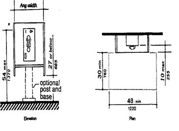
Page 90
(3) Mounting Height. The
highest operable part of the telephone shall be within the reach ranges
specified in rule 120-3-20-.12(5) or rule 120-3-20-.13(6).
Note: In localities where the dial-tone
first system is in operation, calls can be placed at a coin telephone through
the operator without inserting coins. .The operator button is located at a
height of 46 inches (1170 mm) if the coin slot of the telephone is at 54 inches
(1370 mm). A generally available public telephone with a coin slot mounted
lower on the equipment would allow universal
installation of telephones at a height of 48 inches (1220
mm) or less to all operable parts.
(4) Protruding Objects. Telephones shall
comply with rule 120-3-20-.15.
(5) Hearing Aid Compatible and
Volume Control Telephones Required
by rule 120-3-20-.03.
(a) Telephones shall
be hearing aid compatible.
(b) Volume controls,
capable of a minimum of 12 dbA and a maximum of 18 dbA above normal, shall be
provided in accordance with 4.1.3. If an automatic reset is provided then 18
dbA may be exceeded.
(6) Controls. Telephones
shall have push-button controls where service for such equipment is available.
(7) Telephone Books. Telephone
books, if provided, shall be located in a position that complies with the reach
ranges specified in rule 120-3-2003(5) and rule 120-3-20-.13(6).
(8) Cord Length. The
cord from the telephone to the handset shall be at least 29 inches (735
mm) long.
Fig. 44(b)
Forward Reach Required
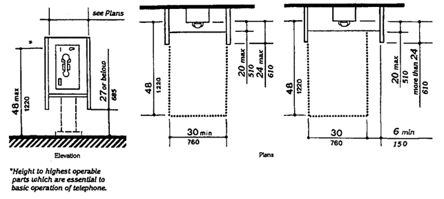
Page 91
(9) Text Telephones Required by
120-3-20-.03.
(a) Text telephones
used with a pay telephone shall be permanently affixed within, or adjacent to,
the telephone enclosure. If an acoustic coupler is used, the telephone cord
shall be sufficiently long to allow connection of the text telephone and the
telephone receiver.
(b) Pay telephones designed to accommodate a
portable text telephone shall be equipped with a shelf and an electrical outlet
within or adjacent to the telephone enclosure. The telephone handset shall be
capable of being placed flush on the surface of the shelf. The shelf shall be
capable of accommodating a text telephone and shall have 6 inches (152 mm)
minimum vertical clearance in the area where the text telephone is to be
placed.
(c) Equivalent facilitation may be provided. For
example, a portable text telephone may be made available in a hotel at the
registration desk if it is available on a 24-hour basis for use with nearby
public pay telephones. In this instance, at least one pay telephone shall
comply with paragraph 2 of this section. In addition, if an acoustic coupler is
used, the telephone handset cord shall be sufficiently long so as to allow
connection of the text telephone and the telephone receiver. Directional
signage shall be provided and shall comply with 120-3-20-.41(7).
Note: A public text telephone may be an
integrated text telephone pay phone unit or a conventional portable text
telephone that is permanently affixed within, or adjacent to, the telephone
enclosure. In order to be usable with a pay phone, a text telephone which is
not a single integrated text telephone pay phone unit will require a shelf
large enough (10 inches (255 mm) wide by 10 inches (255 mm) deep with a 6
inches (150 mm) vertical clearance minimum) to accommodate the device, an
electrical outlet, and a power cord. Movable or portable text telephones may be
used to provide equivalent facilitation. A text telephone should be readily available
so that a person using it may access the text telephone easily and
conveniently. As currently
designed, pocket-type text
telephones for personal use do not accommodate a wide range of
users. Such devices would not be considered substantially equivalent to
conventional text telephones. However, in the future as technology develops
this could change.
Fig. 43(c)
International TDD Symbol

Page 92
120-3-20-.43 Fixed or Built-in Seating
and Tables
(1) Minimum Number. Fixed
or built-in seating or tables required to be accessible by rule 120-3-20-.03
shall comply with rule 120-3-20-.43.
(2) Seating. If seating spaces for people in
wheelchairs are provided at fixed tables or counters, clear floor space
complying with rule 120-3-20-.13(4) shall be provided. Such clear floor space
shall not overlap knee space by more than 19 inches (485 mm) (see Fig. 45).
Fig. 45
Minimum Clearances for Seating and
Tables
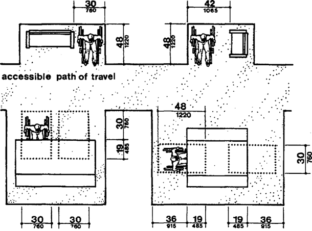
(3) Knee Clearances. If
seating for people in wheelchairs is provided at tables or counters, knee
spaces at least 27 inches (685 mm) high, 30 inches (760 mm) wide,
and 19 inches (485 mm) deep shall be provided (see Fig. 45).
(4) Height of Tables or Counters. The
tops of accessible tables and counters shall be from 28 inches to 34 inches (710
mm to 865 mm) above the finish floor or ground.
93
Page TABLE A1 -CONVENIENT HEIGHTS OF
TABLES AND COUNTERS FOR SEATED PEOPLE1
|
CONDITIONS OF USE
|
SHORT PEOPLE
|
TALL PEOPLE
|
|
inches
|
mm
|
inches
|
mm
|
|
Seated in a wheelchair: Manual work-
Desk or removable armrests
|
26
|
660
|
30
|
760
|
|
Fixed, full-size armrests2
|
323
|
815
|
323
|
815
|
|
Light,
detailed work:
Desk or removable armrests
|
29
|
735
|
34
|
865
|
|
Fixed, full-size armrests2
|
323
|
815
|
34
|
865
|
|
Seated in a 16 inches (405 mm)high chair: Manual
work
|
26
|
660
|
27
|
685
|
|
Light, detailed work
|
28
|
710
|
31
|
785
|
1 All dimensions
are based on a work-surface thickness of 1 1/2 inches (38 mm) and
a clearance of 1 1/2 inches (38 mm) between legs and the underside of a
work surface. People who sit will be using the same counter area.
2 This type of wheelchair arm does
not interfere with the positioning of a wheelchair under a work surface.
3 This dimension is limited by the
height of the armrests: a lower height would be preferable. Some people in this
group prefer lower work surfaces, which require positioning the wheelchair back
from the edge of the counter.
Note: Different types of work require
different table or counter heights for comfort and optimal performance. Light
detailed work such as writing requires a table or counter close to elbow height
for a standing person. Heavy manual work such as rolling dough requires a
counter or table height about 10 inches (255 mm) below elbow height for a
standing person. This principle of high/low table or counter heights also
applies for seated persons; however, the limiting condition for seated manual
work is clearance under the table or counter.
Table A1 shows convenient counter heights for seated persons.
The great variety of heights for comfort and optimal performance indicates a
need for alternatives or a compromise in height if people who stand and people
who sit will be using the same counter area.
Fig. 6
(c)
Maximum Side Reach over Obstruction; Side
Reach
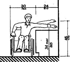
Page 94
120-3-20-.44 Assembly Areas
(1) Minimum Number.
Assembly and associated areas required to be accessible by rule 120-3-20-.03
shall comply with rule 120-3-20-.44.
(2) Size of Wheelchair Locations. Each
wheelchair location shall provide minimum clear ground or floor spaces as shown
in Fig. 46 (a) or
Note: Spaces large enough for two
wheelchairs allow people who are coming to a performance together to sit
together.
(3) Placement
of Wheelchair
Locations. Wheelchair areas shall be an integral part of any
fixed seating plan and
shall be provided
so as to provide
people with physical disabilities a choice
of admission
prices and lines of sight comparable to those for members of the
general public. They shall
adjoin an accessible route that also serves as a means of egress in case of
emergency. At least one companion fixed seat shall be provided next
to each wheelchair seating area. When the
seating capacity
exceeds 300, wheelchair spaces shall be provided in more than one location. Readily
removable seats may be installed in wheelchair spaces when the spaces are not
required to accommodate wheelchair users.
EXCEPTION: Accessible viewing positions
may be clustered for bleachers, balconies, and other areas having sight lines
that require slopes of greater than 5 percent. Equivalent accessible viewing
positions may be located on levels having accessible egress.
Fig. 46(a)
Forward or Rear Access
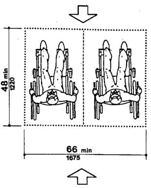
Fig. 46(b) Side Access
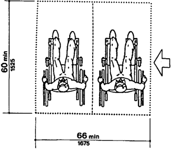
Page 95
Note: The location of wheelchair areas
can be planned so that a variety of positions within the seating area are
provided. This will allow choice in viewing and price categories. Building/life
safety codes set minimum distances between rows of fixed seats with
consideration of the number of seats in a row, the exit aisle width and
arrangement, and the location of exit doors. "Continental" seating,
with a greater number of seats per row and a commensurate increase in row
spacing and exit doors, facilitates emergency egress for all people and
increases ease of access to mid-row seats especially for people who walk with
difficulty. Consideration of this positive attribute of "continental"
seating should be included along with all other factors in the design of fixed
seating areas.
(4) Surfaces. The ground or floor at wheelchair
locations shall be level and shall comply with rule 120-3-20-.16.
(5) Access to
Performing Areas. An accessible route shall connect wheelchair seating
locations with performing areas, including stages, arena floors, dressing
rooms, locker rooms, and other spaces used by performers.
(6) Placement of Listening Systems. If the
listening system provided serves individual fixed
seats, then such seats shall be located within a 50 feet (15 m) viewing
distance of the stage or playing area and shall have a complete view of the
stage or playing area.
Note: A distance of 50 feet (15 m) allows a person to distinguish
performers' facial expressions.
(7) Types of Listening Systems. Assistive listening
systems (ALS) are intended to augment standard public address and audio systems
by providing signals which can be received directly by persons with special
receivers or their own hearing aids and which eliminate or filter background
noise. The type of Assistive listening system appropriate for a particular
application depends on the characteristics of the setting, the nature of the
program, and the intended audience. Magnetic induction loops, infra red and
radio frequency systems are types of listening systems which are appropriate
for various applications.
Fig. 46(a) Forward or Rear Access
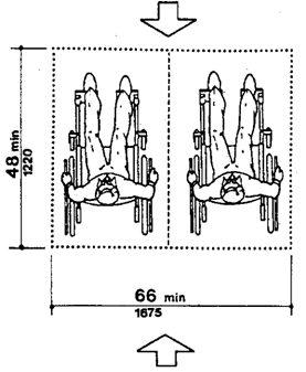
Page 96
Note: An Assistive listening
system appropriate for an assembly area for a group of persons or where the
specific individuals are not known in advance, such as a playhouse, lecture
hall or movie theater, may be different from the system appropriate for a
particular individual provided as an auxiliary aid or as part of a reasonable
accommodation. The appropriate device for an individual is the type that
individual can use, whereas the appropriate system for an assembly area will
necessarily be geared toward the "average" or aggregate needs of
various individuals. A listening
system that can be used from any seat in a seating area is the
most flexible way to meet this specification. Earphone jacks with variable
volume controls can benefit only people who have slight hearing loss and do not
help people who use hearing aids. At the present time, magnetic induction loops
are the most feasible type of listening system for people who use hearing aids
equipped with "T-coils," but people without hearing aids or those
with hearing aids not equipped with inductive pick-ups cannot use them without
special receivers. Radio frequency systems can be extremely effective and
inexpensive. People without hearing aids can use them, but people with hearing
aids need a special receiver to use them as they are presently designed. If
hearing aids had a jack to allow a by-pass of microphones, then radio frequency
systems would be suitable for people with and without hearing aids. Some
listening systems may be subject to interference from other equipment and
feedback from hearing aids of people who are using the systems. Such
interference can be controlled by careful engineering design that anticipates
feedback sources in the surrounding area.
Table A2, reprinted from a National Institute of
Disability and Rehabilitation Research "Rehab Brief,"
shows some of the advantages and disadvantages of different types of Assistive
listening systems. In addition, the Architectural and Transportation Barriers
Compliance Board (Access Board) has published a pamphlet on Assistive Listening
Systems which lists demonstration centers across the country where technical
assistance can be obtained in selecting and installing appropriate systems. The
state of New York has also adopted a detailed technical specification which may
be useful.
Page 97
Table A2 Summary of Assistive Listening Devices
|
SYSTEM
|
ADVANTAGES
|
DISADVANTAGES
|
TYPICAL APPLICATIONS
|
|
Induction Loop
Transmitter:Trans ducer wired to induction loop around
listening area.
Receiver: Self-contained
induction receiver or
personal hearing aid
with telecoil.
|
Cost-Effective
Low Maintenance
Easy to use
Unobtrusive
May be possible to integrate into existing public address
system.
Some hearing aids can function as receivers.
|
Signal spills over to adjacent rooms.
Susceptible to electrical interference.
Limited portability Inconsistent signal strength
Head position affects signal strength.
Lack of standards for induction coil performance.
|
Meeting areas
Theaters
Churches and Temples
Conference rooms
Classrooms
TV viewing
|
|
FM
Transmitter: Flashlight-sized worn by speaker.
Receiver: With
personal hearing
aid via DAI or
induction
neck-loop
and telecoil; or
self-contained
with earphone(s).
|
Highly portable
Different channels allow use by different groups within the
same room.
High user mobility
Variable for large range of hearing losses.
|
High cost of receivers
Equipment fragile
Equipment obtrusive
High maintenance
Expensive to maintain
Custom fitting to individual user may be required.
|
Classrooms Tour groups Meeting areas Outdoor events One-on-one
|
|
Infrared
Transmitter: Emitter in
line-of-sight with receiver.
Receiver: Self-contained.
Or with personal hearing aid via DAI or induction neckloop and
Otelecoil.
|
Easy to use
Insures privacy or
confidentiality
Moderate cost
Can often be integrated into exiting public address system.
|
Line-of-sight required between emitter and receiver.
Ineffective outdoors
Limited portability
Requires installation
|
Theaters
Churches and Temples
Auditoriums
Meetings requiring confidentiality
TV viewing
|
Source: Rehab Brief, National Institute on Disability and
Rehabilitation Research, Washington, DC, Vol. XII, No. 10, (1990).
Page 98
120-3-20-.45 Automated Teller
Machines
(1) General. Each machine required to be
accessible by rule 120-3-20-.03 shall be on an accessible route and shall
comply with rule 120-3-20-.45.
(2) Clear Floor Space. The automatic teller
machine shall be located so that clear floor space complying with rule
120-3-20-.13(2) is provided to allow a person using a wheelchair to make a
forward approach, parallel approach, or both, to the machine.
(3) Reach Ranges.
(a) Forward Approach
Only. If only a forward approach is possible, operable parts of all controls
shall be placed within the forward reach range specified in rule 120-3-20-.13(5).
(b) Parallel Approach Only. If only a parallel
approach is possible, operable parts of controls shall be placed as
follows:
1. Reach Depth Not
More than 10 inches (255 mm). Where the reach depth to the operable
parts of all controls as measured from the vertical plane perpendicular to the
edge of the unobstructed clear floor space at the farthest protrusion of the
automated teller machine or surround is not more than 10 in (255 mm), the
maximum height above the finished floor or grade shall be 54 in (1370 mm).
2. Reach Depth More than 10 inches (255 mm). Where
the reach depth to the operable parts of any control as measured from the
vertical plane perpendicular to the edge of the unobstructed clear floor space
at the farthest protrusion of the automatic teller machine or surround is more
than 10 inches (255 mm), the maximum height above the finished floor or grade
shall be as follows:
|
Reach Depth
|
Maximum Height
|
|
Inches
|
mm
|
Inches
|
mm
|
|
10
|
255
|
54
|
1370
|
|
11
|
280
|
53 1/2
|
1360
|
|
53
|
1345
|
|
12
|
305
|
52 1/2
|
1335
|
|
13
|
330
|
51 1/2
|
1310
|
|
14
|
355
|
51
|
1295
|
|
15
|
380
|
50 1/2
|
1285
|
|
16
|
405
|
50
|
1270
|
|
17
|
430
|
49 1/2
|
1255
|
|
49
|
1245
|
|
18
|
455
|
48 1/2
|
1230
|
|
19
|
485
|
47 1/2
|
1205
|
|
20
|
510
|
47
|
1195
|
|
21
|
535
|
46 1/2
|
1180
|
|
22
|
560
|
46
|
1170
|
|
23
|
585
|
|
|
|
24
|
610
|
|
|
3. Forward and
Parallel Approach. If both a forward and parallel approach are possible,
operable parts of controls shall be placed within at least one of the reach
ranges in paragraphs (a) or
(b) of this section.
4. Bins. Where bins are provided for envelopes,
waste paper, or other purposes, at least one of each type provided shall comply
with the applicable reach ranges in paragraphs (a), (b), or
(c) of this section.
Page 99
EXCEPTION: Where a function can be performed in a
substantially equivalent manner by using an alternate control, only one of the
controls needed to perform that function is required to comply with this
section. If the controls are identified by tactile markings, such marking shall
be provided on both controls.
(4) Controls.
Controls for user activation shall comply with rule 120-3-20-.38(4).
(5) Equipment for
Persons with Vision Impairments. Instructions and all information for use shall
be made accessible to and independently usable by persons with vision
impairments.
120-3-20-.46 Dressing and Fitting Rooms
(1) General.
Dressing and fitting rooms required to be accessible by rule 120-3-20-.03 shall
comply with rule 120-3-20-.46 and shall be on an accessible route.
(2) Clear Floor Space. A clear floor space allowing
a person using a wheelchair to make a 180-degree turn shall be provided in
every accessible dressing room entered through a swinging or sliding door. No
door shall swing into any part of the turning space. Turning space shall not be
required in a private dressing room entered through a curtained opening at
least 32 inches (815 mm) wide if clear floor space complying with rule
120-3-20-.13 renders the dressing room usable by a person using a wheelchair.
(3) Doors. All doors
to accessible dressing rooms shall be in compliance with rule 120-3-20-.24.
(4) Bench. Every
accessible dressing room shall have a 24 inches by 48 inches bench fixed to the
wall along the longer dimension. The bench shall be mounted 17 inches to 19
inches (430 mm to 485 mm) above the finish floor. Clear floor space shall be
provided alongside the bench to allow a person using a wheelchair to make a
parallel transfer onto the bench. The structural strength of the bench and
attachments shall comply with rule 120-3-20.37(3). Where installed in
conjunction with showers, swimming pools, or other wet locations, water shall
not accumulate upon the surface of the bench and the bench shall have a
slip-resistant surface.
(5) Mirrors. Where
mirrors are provided in dressing rooms of the same use, then in an accessible
dressing room, a full-length mirror, measuring at least 18 inches wide by 54
inches high (460 mm by 1370 mm), shall be mounted in a position affording a
view to a person on the bench as well as to a person in a standing position.
Page 100
120-3-20-.47
Restaurants And Cafeterias
(1) General. Except
as specified or modified in this section, restaurants and cafeterias shall
comply with the requirements of rule 120-3-20-.03 to rule 120-3-20-.52.
Where fixed tables (or dining counters where food is consumed
but there is no service) are provided, at least 5 percent, but not
less than one, of the fixed tables (or a portion of the dining counter) shall
be accessible and shall comply with rule 120-3-20-.43 as required
in rule
120-3-20-.08 (18) . In
establishments
where separate areas are designated for smoking and nonsmoking patrons, the
required number of accessible fixed tables (or counters) shall be
proportionally distributed between the smoking and nonsmoking areas. In new
construction, and where
practicable in alterations, accessible fixed tables (or
counters) shall be distributed throughout the space or facility.
Note: Dining counters (where there is no
service) are
Fig. 53 Food Service Lines
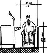
typically found in small carry-out restaurants, bakeries, or
coffee shops and may be only a narrow eating surface attached to a wall. This
section requires that where such a dining counter is provided, a portion of the
counter shall be at the required accessible height.
(2) Counters
and Bars. Where food or drink is served at counters exceeding 34 inches
(8 65 mm) in height for consumption by customers seated on stools or standing
at the counter, a portion of the main counter which is 60 inches (1525 mm) in
length minimum shall be provided in compliance with rule 120-3-20-.43 or
service shall be available at accessible tables within the same area.
(3) Access
Aisles. All
accessible fixed tables shall be accessible by means of an
access aisle at least 36 inches (915 mm) clear between parallel edges of tables
or between a wall and the table edges.
(4) Dining
Areas. In new
construction, all dining areas, including raised or sunken
dining areas, loggias, and outdoor seating areas, shall be accessible. In
buildings without elevators, an accessible means of vertical access to the
mezzanine is not required under the following conditions:
Page 101
(a) the area of mezzanine seating
measures no more than 33 percent of the area of the total accessible seating
area;
(b) the same services and decor are
provided in an accessible space usable by the general public; and,
(c) the accessible areas are not
restricted to use by people with disabilities. In alterations, accessibility to
raised or sunken dining areas, or to all parts of outdoor seating areas is not
required provided that the same services and decor are provided in an
accessible space usable by the general public and are not restricted to use by
people with disabilities.
(5) Food Service Lines. Food
service lines shall have a minimum clear width of 36 inches, with a preferred
clear width of 42 inches to allow passage around a person using a wheelchair.
Tray slides shall be mounted no higher than 34 inches above the floor
(see Fig. 53}. If self-service shelves are provided, at least 50 percent of
each type must be within reach ranges specified in rule 120-3-20-.13 (5} and
rule 120-3-20-.13(6) .
Fig. 53 Food Service Lines
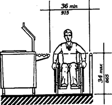
Fig. 54 Tableware Areas
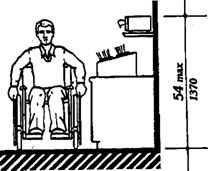
(6) Tableware and Condiment Areas. Self-service
shelves and dispensing devices for tableware, dish ware, condiments, food and
beverages shall be installed to comply with rule 120-3-20-.13 (see Fig. 54).
(7) Raised Platforms. In banquet
rooms or spaces where a head table or speaker's lectern is located on a raised
platform, the platform shall be accessible in compliance with rule
120-3-20-.19 or rule 120-3-20-.22 . Open edges of a raised platform shall be
protected by placement of tables or by a curb.
(8) Vending Machines and Other Equipment. Spaces for
vending machines and other equipment shall comply with rule 120-3-20.13 and
shall be located on an accessible route.
(9) Quiet Areas. (Reserved).
Page 102
120-3-20-.48
Medical Care Facilities
(1) General. Medical
care facilities included in this section are those in which people receive
physical or medical treatment or care and where persons may need assistance in
responding to an emergency and where the period of stay may exceed twenty-four
hours. In
addition to the requirements of rules 120-3-20-.03 through 120-3-20-.52,
medical
care facilities shall comply with rule 120-3-20-.48.
(a) Hospitals - general purpose hospitals,
psychiatric facilities, detoxification facilities - at least
10 percent
of
patient bedrooms and toilets, and all public use and
common use areas are required to be designed and constructed to be
accessible.
(b) Hospitals and rehabilitation facilities that
specialize in treating conditions that affect mobility, or units within either
that specialize in treating conditions that affect mobility -All
patient bedrooms and toilets, and all public use and common use areas
are required to be designed and constructed to be accessible.
(c) Long term care facilities, nursing homes at
least
50
percent of patient bedrooms and toilets, and all
public
use and common use areas are required to be designed and constructed to be
accessible.
(d) Alterations to patient bedrooms:
(1) When patient bedrooms are being added or
altered as part of a planned renovation of an entire wing, a department, or
other discrete area of an existing medical facility, a
percentage of the patient bedrooms that are being added or altered shall comply
with rule 120-3-20-.48 (3) . The percentage of accessible rooms provided
shall be consistent with the percentage of rooms required to be accessible by
the applicable requirements of rules 120-3-20-.48(l)(a), 120-3-20-.48(l)(b),
or
120-3-20-.48(l)(c),
until the number of accessible patient bedrooms in the facility equals the
overall number that would be required if the facility were newly constructed.
(For example, if 20 patient bedrooms are being altered in the obstetrics
department of a hospital, 2 of the altered rooms must be made accessible. If,
within the same hospital, 20 patient bedrooms are being altered in a unit that
specializes in treating mobility impairments, all of the altered rooms must be
made accessible.) Where toilet/bathrooms are part of patient bedrooms which are
added or altered and required to be accessible, each such patient
toilet/bathroom shall comply with rule 120-3-20-.48(4).
(b) When patient bedrooms are being added or
altered individually, and not as part of an alteration of the entire area,
Page 103
the altered patient bedrooms shall comply with rule
120-3-20-.48(3), unless either:
a) the number of accessible rooms provided in the
department or area containing the altered patient bedroom equals the number of
accessible patient bedrooms that would be required if the percentage requirements
of rules
120-3-20-.48(l)(a), 120-3-20-.48(l)(b), or 120-3-20-,48(l)(c) were
applied to that department or area; or
b) the number of accessible patient
bedrooms in the facility equals the overall number that would be required if
the facility were newly constructed. Where toilet/bathrooms are part of patient
bedrooms which are added or altered and required to be accessible, each such
toilet/bathroom shall comply with rule 120-3-20-.48(4) .
(2) Entrances. At least
one accessible entrance that complies with rule 120-3-20-.25
shall be protected from the weather by canopy or roof overhang. Such entrances
shall incorporate a passenger loading zone that complies with rule 120-3-20-
.17(6).
(3) Patient Bedrooms. Provide
accessible patient bedrooms in compliance with rules
120-3-20-.03 through 120-3-20-.46. Accessible
patient bedrooms shall comply with the following:
(a) Each bedroom shall have a door that complies
with rule
120-3-20-.24.
(b) Each bedroom shall have adequate
space to provide a maneuvering space that complies with rule
120-3-20-. 13(3). In rooms with 2 beds, it is preferable that this
space be located between beds.
(c) Each bedroom shall have adequate space to
provide a minimum clear floor space of 36 inches {915 mm)
along each side of the bed and to provide an accessible route complying with rule
120-3-20-.14(3) to each side of each bed.
(4)
Patient Toilet Rooms.
Where toilet/bath rooms are provided as a part of a patient
bedroom, each patient bedroom that is required to be accessible shall have an
accessible toilet/bath room that complies with rule 120-3-20-.33 or rule
12
0-3-20-.34 and shall be on an accessible route.
Page 104
120-3-20-.49
Business and Mercantile
(1) General. In
addition to the requirements of rules 120-3-20-.03 through
120-3-20-.46,
the
design of all areas used for business transactions with the public shall comply
with rule 120-3-20-.49.
(2) Sales and Service Counters, Teller
Windows, Information Counters.
(a) In department
stores and miscellaneous retail stores where counters have cash registers and
are provided for sales or distribution of goods or services to the public, at
least one of each type shall have a portion of the counter which is at least 36
inches (915mm) in length with a maximum height of 36 inches (915 mm)
above the finish floor. It shall be on an accessible route complying with rule
120-3-20-.14. The accessible counters must be dispersed throughout the building
or facility. In alterations where it is technically infeasible to
provide an accessible counter, an auxiliary counter meeting these requirements
may be provided.
(b) At ticketing
counters, teller stations in a bank, registration counters in hotels and
motels, box office ticket counters, and other counters that may not have a cash
register but at which goods or services are sold or distributed, either:
1. a portion of the
main counter which is a minimum of 36 inches (915 mm) in length shall be
provided with a maximum height of 36 inches (915 mm); or
2. an auxiliary
counter with a maximum height of 36 inches (915 mm) in close proximity to the
main counter shall be provided; or
3. equivalent
facilitation shall be provided (e.g., at a hotel registration counter,
equivalent facilitation might consist of:
(i) provision of a
folding shelf attached to the main counter on which an individual with
disabilities can write, and
(ii) use of the space
on the side of the counter or at the concierge desk, for handing materials back
and forth). All accessible sales and service counters shall be on an accessible
route complying with rule 120-3-20-.14
(c) Assistive Listening Devices. (Reserved)
Note: At
all sales and service counters, teller windows, box offices, and information
kiosks where a physical barrier separates service personnel and customers, it
is recommended that at least one permanently installed Assistive listening
device complying
with rule 120-3-20-.44 be
provided at each location or series. Where Assistive listening devices are
installed, signage should be provided identifying those stations which are so
equipped.
(3) Check out Aisles.
(a) In new
construction, accessible check out aisles shall be provided in conformance with
the table below:
|
Total Check out Aisles of Each Design
|
Minimum Number of Accessible
Check out Aisles of Each Design
|
|
1-4 5-8
|
1
2
|
|
8-15 over 15
|
3 plus 20% of additional aisles
|
Page 105
EXCEPTION: In new construction, where the selling
space is less than 5000 square feet, only one check out aisle is
required to be accessible.
EXCEPTION: In alterations, at least one check out
aisle shall be accessible in facilities less than 5000 square feet of selling
space. In facilities of 5000 or more square feet of selling space, at least one
of each design of check out aisle shall be made accessible when altered until
the number of accessible check out aisles of each design equals the number
required in new construction.
Examples of check out aisles of different
"design" include those which are specifically designed to serve
different functions. Different "design" includes but is not limited
to the following features: length of belt or no belt; or permanent signage
designating the aisle as an express lane.
(b) Clear aisle width for accessible check out
aisles shall comply with rule 120-3-3-20-. 13(1) and maximum adjoining
counter height shall not exceed 38 inches (965 mm) above the finish floor.
The top of the lip shall not exceed 40 inches (1015 mm) above the finish floor.
(c) Signage
identifying accessible check out aisles shall comply with rule 120-3-20.41(7)
and shall be mounted above the check out aisle in the same location where the
check out number or type of check out is displayed.
Note: Rule 120-3-20-.49(2) refers to counters
without aisles; rule 120-3-20-.49(3) concerns check out aisles. A counter
without an aisle (rule 120-3-20-.49(2)) can be approached from more than one
direction such as in a convenience store. In order to use a check out aisle
(rule 120-3-20-.49(3)), customers must enter a defined area (an aisle) at a
particular point, pay for goods, and exit at a
particular point.
(4) Security Bollards. Any device used to prevent
the removal of shopping carts from store premises shall not prevent access or
egress to people in wheelchairs. An alternate entry that is equally
convenient to that provided for the ambulatory population is acceptable. (1) General.
In addition to the requirements of
120-3-20-.50 Libraries
rules 120-3-20-.03 to 120-3-20-.46, the design of
all public areas of a library shall comply with rule 120-3-20-.50, including
reading and study areas, stacks, reference rooms, reserve areas, and special
facilities or collections.
(2) Reading and Study Areas. At
least 5 percent or a minimum of one of each element of fixed seating,
tables, or study carrels shall comply with rule 120-3-20-.13 and rule
120-3-20-.43. Clearances between fixed accessible tables and between study
carrels shall comply with rule 120-3-20-.14.
(3) Check-Out Areas. At
least one lane at each check out area shall comply with rule
120-3-20-.49(2)(a). Any traffic control or book security gates or turnstiles
shall comply with rule 120-3-20-.24.
(4) Card Catalogs and Magazine Displays.
Minimum clear aisle space at card catalogs and
magazine displays shall comply with Fig. 55. Maximum reach height shall comply
with rule 120-3-20-.13, with a height of 48 inches (1220 mm) preferred
irrespective of approach allowed.
Page 106
(5) Stacks. Minimum
clear aisle width between stacks shall comply with rule 120-3-20-.14, with a
minimum clear aisle width of 42 inches (1065 mm) preferred where possible.
Shelf height in stack areas is unrestricted (see Fig. 56).
Fig. 55 Card Catalog
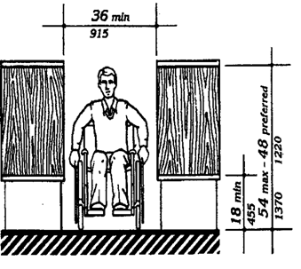
Fig. 56 Stacks
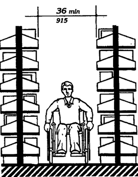
Page 107
120-3-20-.51 Accessible Transit Lodging
Except as specified in the special technical
provisions of this section, accessible transient lodging shall comply with the
applicable requirements of rules 120-3-20-.03 through 120-3-20-.46. Transient
lodging includes facilities or portions thereof used for sleeping
accommodations, when not classed as a medical care facility.
(1) Hotels, Motels, Inns, Boarding
Houses, Dormitories, Resorts and Other Similar Places of Transient Lodging.
(a) General. All
public use and common use areas are required to be designed and constructed to
comply with rule 120-3-20-.03 (Accessible Elements and Spaces: Scope and
Technical Requirements).
EXCEPTION: Rules 120-3-20-.51(l)
through 120-3-20-.51(4) do not apply to an establishment
located within a building that contains not more than five rooms for rent or
hire and that is actually occupied by the proprietor of such establishment as
the residence of such proprietor.
(b) Accessible Units, Sleeping Rooms,
and Suites. Accessible sleeping rooms or suites that
comply with the requirements of rule 120-3-20-.51(2). (Requirements for
Accessible Units, Sleeping Rooms, and Suites) shall be provided in conformance
with the table below. In addition, in hotels, of 50 or more sleeping
rooms or suites.
additional accessible sleeping rooms or suites that
include a roll-in shower shall also be provided in conformance with the table
below. Such accommodations shall comply with the requirements of rule
120-3-20-.51(2), rule 120-3-20-.32, and Figure 57(a) or (b).
|
Number of Rooms
|
Accessible Rooms
|
Rooms with Roll-in Showers
|
|
1 to 25
|
1
|
|
|
26 to 50
|
2
|
I
|
|
51 to 75
|
3
|
1
|
|
76 to 100
|
4
|
1
|
|
101 to 150
|
5
|
2
|
|
151 to 200
|
6
|
2
|
|
201 to 300
|
7
|
3
|
|
301 to 400
|
8
|
4
|
|
401 to 500
|
9
|
4 plus one for each
additional 100 over 400
|
|
501 to 1000
|
2% of total
|
|
|
1001 and over
|
20 plus 1 for each 100 over 1000
|
|
(c) Sleeping Accommodations for Persons
with Hearing Impairments. In addition to those accessible
sleeping rooms and suites required by rule 120-3-20-.51(2), sleeping rooms and
suites that comply with rule 120-3-20-.51(3) (Visual Alarms, Notification
Devices, and Telephones) shall be provided in conformance with the following
table:
Page 108
|
Number of Elements
|
Accessible Elements
|
|
1 to 25
|
1
|
|
26 to 50
|
2
|
|
51 to 75
|
3
|
|
76 to 100
|
4
|
|
101 to 150
|
5
|
|
151 to 200
|
6
|
|
201 to 300
|
7
|
|
301 to 400
|
8
|
|
401 to 500
|
9
|
|
501 to 1000
|
2% of total
|
|
1001 and over
|
20 plus 1
for
each 100
over
1000
|
(d) Classes of Sleeping Accommodations.
1. In order to provide persons with
disabilities a range of options equivalent to those available to other persons
served by the facility, sleeping rooms and suites required to be accessible by
rule 120-3-20-.51(b) shall be dispersed among the various classes of sleeping
accommodations available to patrons of the place of transient lodging. Factors
to be considered including room size, cost, amenities provided, and the number
of beds provided.
2. Equivalent
Facilitation. For purposes of this section, it shall be deemed equivalent
facilitation if the operator of a facility elects to limit construction of
accessible rooms to those intended for multiple occupancy, provided that such
rooms are made available at the cost of a single occupancy room to an
individual with disabilities who requests a single-occupancy room.
(e) Alterations to Accessible Units,
Sleeping Rooms, and Suites. When sleeping rooms are
being altered in an existing facility, or portion thereof, subject to the
requirements of this section, at least one sleeping room or suite that complies
with the requirements of rule 120-3-20-.51(2) (Requirements for Accessible Units,
Sleeping Rooms, and Suites) shall be provided for each 25 sleeping rooms, or
fraction thereof, of rooms being altered until the number of such rooms
provided equals the number required to be accessible with rule 120-3-20-.51(b).
In addition, at least one sleeping room or suite that complies with the
requirements of rule 120-3-20-51(3) (Visual Alarms, Notification Devices, and
Telephones) shall be provided for each 25 sleeping rooms, or fraction thereof,
of rooms being altered until the number of such rooms equals the number
required to be accessible by rule 120-3-20-.51(c).
(2) Requirements for Accessible Units,
Sleeping Rooms and Suites.
(a) General. Units,
sleeping rooms, and suites required to be accessible by rule 120-3-20-.51(1)
shall comply with rule 120-3-20-.51(2).
(b) Minimum Requirements. An
accessible unit, sleeping room or suite shall be on an accessible route
complying with rule 120-3-20-. 14 and have the following accessible elements
and spaces.
1. Accessible sleeping rooms shall
have a 36 inches (915 mm) clear width maneuvering space located along both
sides of a bed, except that where two beds are provided, this requirement can
be met by providing a 36 inches (915 mm) wide maneuvering space located between
the two beds.
2. An accessible
route complying with rule 120-3-20-. 14 shall connect all accessible spaces and
elements, including telephones, within the unit,
Page 109
sleeping room, or suite. This is not intended to
require an elevator in multistory units as long as the spaces identified in
rule 120-3-20-.51(2)(b)(6) and rule 120-3-20-.51(2)(b)(7) are on accessible
levels and the accessible sleeping area is suitable for dual occupancy.
3. Doors and
doorways designed to allow passage into and within all sleeping rooms, suites
or other covered units shall comply with rule 120-3-20-.24.
4. If fixed or
built-in storage facilities such as cabinets, shelves, closets, and drawers are
provided in accessible spaces, at least one of each type provided shall contain
storage space complying with rule 120-3-20-.36. Additional storage may be
provided outside of the dimensions required by rule 120-3-20-.36.
5. All controls in
accessible units, sleeping rooms, and suites shall comply with rule
120-3-20-.38.
6. Where provided
as part of an accessible unit, sleeping room, or suite, the following spaces
shall be accessible and shall be on an accessible route:
(a) the living area.
(b) the dining area.
(c) at least one sleeping area.
(d) patios, terraces, or balconies.
EXCEPTION: The requirements of rule 120-3-20-.24(8)
and rule 120-3-20-.14(8) do not apply where it is necessary to utilize a higher
door threshold or a change in level to protect the integrity of the unit from
wind/water damage. Where this exception results in patios, terraces or
balconies that are not at an accessible level, equivalent facilitation shall be
provided, (e.g., Equivalent facilitation at a hotel patio or balcony might
consist of providing raised decking or a ramp to provide accessibility).
(e) at least one
full bathroom (i.e., one with a water closet, a lavatory, and a bathtub or
shower).
(f) if only half baths are provided, at least one
half bath.
(g) carports, garages or parking spaces.
7. Kitchens, Kitchenettes, or Wet Bars. When
provided as accessory to a sleeping room or suite, kitchens, kitchenettes, wet
bars, or similar amenities shall be accessible. Clear floor space for a front
or parallel approach to cabinets, counters, sinks, and appliances shall be
provided to comply with rule 120-3-20-.13(4). Countertops and sinks shall be
mounted at a maximum height of 34 inches (865 mm) above the floor. At least
fifty percent of shelf space in cabinets or refrigerator /freezers shall be
within the reach ranges of rule 120-3-20-.13(5) or rule 120-3-20-. 13(6) and
space shall be designed to allow for the operation of cabinet and/or appliance
doors so that all cabinets and appliances are accessible and usable. Controls
and operating mechanisms shall comply with rule 120-3-20-.38.
8. Sleeping room
accommodations for persons with hearing impairments required by rule
120-3-20-.51 and complying with rule 120-3-20-.51(3) shall be provided in the
accessible sleeping room or suite.
(3) Visual Alarms,
Notification Devices and Telephones.
(a) General. In sleeping rooms required to comply
with this section, auxiliary visual alarms shall be provided and shall comply
with rule 120-3-20-.39(4). Visual notification devices shall also be provided
in units, sleeping rooms and suites to alert room occupants of incoming
telephone calls and a door knock or bell. Notification devices
Page 110
shall not be connected to auxiliary visual alarm
signal appliances. Permanently installed telephones shall have volume controls
complying with rule 120-3-20-.42(5); an accessible electrical outlet within 4
feet (1220 mm) of a telephone connection shall be provided to facilitate the
use of a text telephone.
(b) Equivalent Facilitation. For
purposes of this section, equivalent facilitation shall include the
installation of electrical outlets (including outlets connected to a facility's
central alarm system) and telephone wiring in sleeping rooms and suites to
enable persons with hearing impairments to utilize portable visual alarms and
communication devices provided by the operator of the facility.
(4) Other Sleeping Rooms and Suites. Doors
and doorways designed to allow passage into and within all sleeping units or
other covered units shall comply with rule 120-3-20-.24(5).
(5) Transient Lodging in Homeless
Shelters, Halfway Houses, Transient Group Homes, and Other Social Service
Establishments.
(a) New Construction. In
new construction all public use and common use areas are required to be
designed and constructed to comply with rule 120-3-20.08. At least one
of each type of amenity (such as washers, dryers and similar equipment
installed for the use of occupants) in each common area shall be accessible and
shall be located on an accessible route to any accessible unit or sleeping
accommodation.
EXCEPTION:
Where elevators are not provided as allowed in rule
120-3-20-.08(5), accessible amenities are not required on inaccessible floors
as long as one of each type is provided in common areas on accessible floors.
(b) Alterations.
1. Social service
establishments which are not homeless shelters:
(i) The provisions of rule 120-3-20-.51(5)(c) and
rule 120-3-20-.51(l)(e) shall apply to sleeping rooms and beds.
(ii) Alteration of
other areas shall be consistent with the new construction provisions of rule
120-3-20-.51(5)(a).
(2) Homeless shelters. If the following elements are
altered, the following requirements apply:
(a) at least one public entrance shall allow a
person with mobility impairments to approach, enter and exit including a
minimum clear door width of 32 inches (815 mm).
(b) sleeping space for homeless persons as provided
in the scoping provisions of rule 120-3-20-.51(l)(b) shall include doors to the
sleeping area with a minimum clear width of 32 inches (815 mm) and maneuvering
space around the beds for persons with mobility impairments complying with rule
120-3-20-.51(2)(a).
(c) at least one toilet room for each sex or one
unisex toilet room shall have a minimum clear door width of 32 inches (815 mm),
minimum turning space complying with rule 120-3-20-.13(3), one water closet
complying with rule 120-3-20-.27, one lavatory complying with rule 120-3-20-.30
and the door shall have a privacy latch; and, if provided, at least one tub or
shower shall comply with rule 120-3-20-.31 or rule 120-3-20-.32, respectively.
(d) at least one
common area which a person with mobility impairments can approach, enter and
exit including a minimum clear door width of 32 inches.
Page 111
(e) at least one route connecting elements (a), (b),
(c) and (d) which a person with mobility impairments can use including minimum
clear width of 36 inches (915 mm), passing space complying with rule
120-3-20-.14(4), turning space complying with rule 120-3-20-.14(3) and changes
in levels complying with rule 120-3-20-.14(8).
(f) homeless
shelters can comply with the provisions of (a)-(e) by providing the above
elements on one accessible floor.
(3) Accessible
Sleeping Accommodations in New Construction. Accessible sleeping rooms shall be
provided in conformance with the table in rule 120-3-20-.51(l)(b) and shall
comply with rule 120-3-20-.51(2) Accessible Units, Sleeping Rooms and Suites
(where the items are provided). Additional sleeping rooms that comply with rule
120-3-20-.51(3) Sleeping Accommodations for Persons with Hearing Impairments
shall be provided in conformance with the table provided in rule 120-3-20-.5
l(l)(c). In facilities with multi-bed rooms or spaces, a percentage of the beds
equal to the table provided in rule 120-3-20-.51(l)(b) shall comply with rule
120-3-20-.51(2)(b)(l).
120-3-20-.52 Transportation Facilities
(1) General. Every
station, bus stops, bus stop pad, terminal, building or other transportation
facility', shall comply with the applicable provisions of rules 120-3-20-.03
through 120-320-.46, rules 120-3-20-.47 through 120-3-20-.51, and the
applicable provisions of this section. The exceptions for elevators in rule
120-3-20-.08(5), exception 1 and rule 120-3-20-.1 l(l)(k) do not apply to a
terminal, depot, or other station used for specified public transportation, or
an airport passenger terminal, or facilities subject to Title II.
(2) Bus Stops and
Terminals, (a) New Construction.
1. Where new bus
stop pads are constructed at bus stops, bays or other areas where a lift or
ramp is to be deployed, they shall have a firm, stable surface; a minimum clear
length of 96 inches (measured from the curb or vehicle roadway edge) and a
minimum clear width of 60 inches (measured parallel to the vehicle roadway) to
the maximum extent allowed by legal or site constraints; and shall be connected
to streets, sidewalks or pedestrian paths by an accessible route complying with
rule 120-3-20-.14 and rule 120-3-20-.15. The slope of the pad parallel to the
roadway shall, to the extent practicable, be the same as the roadway. For water
drainage, a maximum slope of 1:50 (2%) perpendicular to the roadway is allowed.
2. Where provided,
new or replaced bus shelters shall be installed or positioned so as to permit a
wheelchair or mobility aid user to enter from the public way and to reach a
location, having a minimum clear floor area of 30 inches by 48 inches, entirely
within the perimeter of the shelter. Such shelters shall be connected by an
accessible route to the boarding area provided under paragraph (1) of this
section.
3. Where provided,
all new bus route identification signs shall comply with rule 120-3-20-.41(5).
In addition, to the maximum extent practicable, all new bus route
identification signs shall comply with rule 120-3-20-.41(2) and rule
Page 112
120-3-20-.41(3). Signs that are sized to the maximum
dimensions permitted under legitimate local, state or federal regulations or
ordinances shall be considered in compliance with rale 120-3-20-.41(2) and rule
120-3-20-.41(3) for purposes of this section.
EXCEPTION:
Bus schedules, timetables, or maps that are posted
at the bus stop or bus bay are not required to comply with this provision.
(b) Bus Stop Siting and Alterations.
1. Bus stop sites
shall be chosen such that, to the maximum extent practicable, the areas where
lifts or ramps are to be deployed comply with rule 120-3-20-.52(a)l and 2.
2. When new bus
route identification signs are installed or old signs are replaced, they shall
comply with the requirements of rule 120-3-20-.52(a)3.
(3) Fixed Facilities and Stations, (a)
New Construction.
New stations in rapid rail, light rail, commuter rail,
intercity bus, intercity rail, high speed rail, and other fixed guide way
systems (e.g., automated guide way transit, monorails, etc.) shall comply with
the following provisions, as applicable:
1. Elements such as ramps, elevators
or other circulation devices, fare vending or other ticketing areas, and fare
collection areas shall be placed to minimize the distance which wheelchair
users and other persons who cannot negotiate steps may have to travel compared
to the general public. The circulation path, including an accessible entrance
and an accessible route, for persons with disabilities shall, to the maximum
extent practicable, coincide with the circulation path for the general public.
Where the circulation path is different, signage complying with rules
120-3-20-.41(1), 120-3-20-.41(2), 120-3-20-.41(3), 120-3-20-.41(5), and
120-3-20-.41(7)(l) shall be provided to indicate direction to and identify the
accessible entrance and accessible route.
2. In lieu of
compliance with rule 120-3-20-.08(8), at least one entrance to each station
shall comply with rule 120-3-20-.25, Entrances. If different entrances to a
station serve different transportation fixed routes or groups of fixed routes,
at least one entrance serving each group or route shall comply with rule
120-3-20-.25, Entrances. All accessible entrances shall, to the maximum extent
practicable, coincide with those used by the majority of the general public.
3. Direct
connections to commercial, retail, or residential facilities shall have an
accessible route complying with rule 120-3-20-.14 from the point of connection
to boarding platforms and all transportation system elements used by the
public. Any elements provided to facilitate future direct connections shall be
on an accessible route connecting boarding platforms and all transportation
system elements used by the public.
4. Where signs are provided at entrances to stations
identifying the station or the entrance, or both, at least one sign at each
entrance shall comply with rule 120-3-20-.41(l) 4.30.4 and rule
120-3-20-.4t(6). Such signs shall be placed in uniform locations at entrances
within the transit system to the maximum extent practicable.
EXCEPTION:
Where the station has no defined entrance, but
signage is provided, then the accessible signage shall be placed in a central
location.
Page 113
5. Stations covered
by this section shall have identification signs complying with rules
120-3-20-.41(l), 120-3-20-.41(2), 120-3-20-.41(3), 120-3-20-.41(5), Signs shall
be placed at frequent intervals and shall be clearly visible from within the
vehicle on both sides when not obstructed by another train. When station
identification signs are placed close to vehicle windows (i.e., on the side
opposite from boarding) each shall have the top of the highest letter or symbol
below the top of the vehicle window and the bottom of the lowest letter or
symbol above the horizontal mid-line of the vehicle window.
6. Lists of
stations, routes, or destinations served by the station and located on boarding
areas, platforms, or mezzanines shall comply with rules 120-3-20-.41(l),
120-3-20-.41(2), 120-3-20-.41(3), 120-3-20-.41(5), A minimum of one sign
identifying the specific station and complying with rule 120-3-20-.41(4) and
rule 120-3-20-.41(6) shall be provided on each platform or boarding area. All
signs referenced in this paragraph shall, to the maximum extent practicable, be
placed in uniform locations within the transit system.
7. Automatic fare vending, collection and adjustment
(e.g., add-fare) systems shall comply with rules 120-3-20-.45(2),
120-3-20-.45(3), and 120-3-20-.45(4). At each accessible entrance such devices
shall be located on an accessible route. If self-service fare collection
devices are provided for the use of the general public, at least one accessible
device for entering, and at least one for exiting, unless one device serves
both functions, shall be provided at each accessible point of entry or exit.
Accessible fare collection devices shall have a minimum clear opening width of
32 inches; shall permit passage of a wheelchair; and, where provided, coin or
card slots and controls necessary for operation shall comply with rule
120-3-20-.38. Gates which must be pushed open by wheelchair or mobility aid
users shall have a smooth continuous surface extending from 2 inches above the
floor to 27 inches above the floor and shall comply with rule 120-3-20-.24.
Where the circulation path does not coincide with that used by the general
public, accessible fare collection systems shall be located at or adjacent to
the accessible point of entry or exit.
Note: One means of making control buttons on fare vending
machines usable by persons with vision impairments is to raise them above the
surrounding surface. Those activated by a mechanical motion are likely to be
more detectable. If fare card vending, collection, and adjustment devices are
designed to accommodate fare cards having one tactually distinctive corner,
then a person who has a vision impairment will insert the card with greater
ease. Token collection devices that are designed to accommodate tokens which
are perforated can allow a person to distinguish more readily between tokens
and common coins. Thoughtful placement of accessible gates and fare vending
machines in relation to inaccessible devices will make their use and detection
easier for all persons with disabilities.
8. Platform edges bordering a drop-off and not
protected by platform screens or guard rails shall have a detectable warning.
Such detectable warnings shall comply with rule 120-3-20-.40(2) and shall be 24
inches wide running the full length of the platform drop-off.
Page 114
9. In stations
covered by this section, rail-to-platform height in new stations shall be
coordinated with the floor height of new vehicles so that the vertical
difference, measured when the vehicle is at rest, is within plus or minus 5/8
inch under normal passenger load conditions. For rapid rail, light rail,
commuter rail, high speed rail, and intercity rail systems in new stations, the
horizontal gap, measured when the new vehicle is at rest, shall be no greater
than 3 inches. For slow moving automated guideway "people mover"
transit systems, the horizontal gap in new stations shall be no greater than 1
inch.
EXCEPTION
1: Existing vehicles operating in new stations may have
a vertical difference with respect to the new platform within plus or minus 1
1/2 inches.
EXCEPTION
2: In light rail, commuter rail and intercity rail
systems where it is not operationally or structurally feasible to meet the
horizontal gap or vertical difference requirements, mini-high platforms,
car-borne or platform-mounted lifts, ramps or bridge plates, or similar
manually deployed devices, meeting the applicable requirements of 36 CFR part
1192, or
49 CFR part
38 shall
suffice.
10. Stations shall not be designed or constructed so
as to require persons with disabilities to board or alight from a vehicle at a
location other than one used by the general public.
11. Illumination levels in the areas where signage
is located shall be uniform and shall minimize glare on signs. Lighting along
circulation routes shall be of a type and configuration to provide uniform
illumination.
12. Text Telephones: The following shall be provided
in accordance with rule 120-3-20-.42(9):
(i) If an interior
public pay telephone is provided in a transit facility (as denned by the
Department of Transportation) at least, one interior public text telephone
shall be provided in the station.
(ii) Where four or
more public pay telephones serve a particular entrance to a rail station and at
least one is in an interior location, at least one interior public text
telephone shall be provided to serve that entrance. Compliance with this
section constitutes compliance with rule 120-3-20-.08 (17)(c).
13. Where it is necessary to cross tracks to reach
boarding platforms, the route surface shall be level and flush with the rail
top at the outer edge and between the rails, except for a maximum 2-1/2 inches
gap on the inner edge of each rail to permit passage of wheel flanges. Such crossings
shall comply with rule 120-3-20-.40(5). Where gap reduction is not practicable,
an above-grade or below-grade accessible route shall be provided.
14. Where public address systems are provided to
convey information to the public in terminals, stations, or other fixed
facilities, a means of conveying the same or equivalent information to persons
with hearing loss Or who are deaf shall be provided.
15. Where clocks are provided for use by the general
public, the clock face shall be uncluttered so that its elements are clearly
visible. Hands, numerals, and/or digits shall contrast with the background
either light-on-dark or dark-on-light. Where clocks are mounted overhead,
numerals and/or digits shall comply with rule 120-3-20-.41(3). Clocks shall be
placed in uniform locations throughout the facility and system to the maximum
extent practicable.
Page 115
16. Where provided in below grade stations,
escalators shall have a minimum clear width of 32 inches. At the top and bottom
of each escalator run, at least two contiguous treads shall be level beyond the
comb plate before the risers begin to form. All escalator treads shall be
marked by a strip of clearly contrasting color, 2 inches in width, placed
parallel to and on the nose of each step. The strip shall be of a material that
is at least as slip resistant as the remainder of the tread. The edge of the
tread shall be apparent from both ascending and descending directions.
17. Where provided, elevators shall be glazed or
have transparent panels to allow an unobstructed view both in to and out of the
car. Elevators shall comply with rule 120-3-20-.21.
EXCEPTION: Elevator cars with a clear
floor area in which a 60 inches in diameter circle can be inscribed may be
substitutedfor the minimum car dimensions of rule 120-3-20-.21, Fig. 22.
18. Where provided, ticketing areas shall permit
persons with disabilities to obtain a ticket and check baggage and shall comply
with rule 120-3-20-.49(2).
19. Where provided, baggage check-in and retrieval
systems shall be on an accessible route complying with rule 120-3-20-.14, and
shall have space immediately adjacent complying with rule 120-3-20-. 13. If
unattended security barriers are provided, at least one gate shall comply with
rule 120-3-20-.24. Gates which must be pushed open by wheelchair or mobility
aid users shall have a smooth continuous surface extending from 2 inches above
the floor to 27 inches above the floor.
(b) Existing Facilities: Key Stations.
1. Rapid, light and commuter rail key stations, as
defined under criteria established by the Department of Transportation in
subpart C of 49 CFR part 37 and existing intercity rail stations shall provide
at least one accessible route from an accessible entrance to those areas
necessary for use of the transportation system.
2. The accessible
route required by rule 120-3-20-.52(b)l shall include the features specified in
rules 120-3-20-.52(a)(l), (4)-(9), (11)-(15), and (17)-(19).
3. Where technical
infeasibility in existing stations requires the accessible route to lead from
the public way to a paid area of the transit system, an accessible fare
collection system, complying with rule 120-3-20-.52(a)(7), shall be provided
along such accessible routes.
4. In light rail,
rapid rail and commuter rail key stations, the platform or a portion thereof
and the vehicle floor shall be coordinated so that the vertical difference,
measured when the vehicle is at rest, within plus or minus 1-1/2 inches under
all normal passenger load conditions, and the horizontal gap, measured when the
vehicle is at rest, is no greater than 3 inches for at least one door of each
vehicle or car required to be accessible by 49 CFR part 37.
EXCEPTION 1: Existing vehicles
retrofitted to meet the requirements of 49 CFR 37.93 (one-car-per-train rule) shall
be coordinated with the platform such that, for at least one door, the vertical
difference between the vehicle floor and the platform, measured when the
vehicle is at rest with 50% normal passenger capacity, is within plus or minus
2 inches and the horizontal gap is no greater than 4 inches.
Page 116
EXCEPTION 2: Where it is not
structurally or operationally feasible to meet the horizontal gap or vertical
difference requirements, mini-high platforms, car-borne or platform mounted
lifts, ramps or bridge plates, or similar manually deployed devices, meeting
the applicable requirements of 36 CFR Part 1192 shall suffice.
5. New direct
connections to commercial, retail, or residential facilities shall, to the
maximum extent feasible, have an accessible route complying with rule
120-3-20-.14 from the point of connection to boarding platforms and all
transportation system elements used by the public. Any elements provided to
facilitate future direct connections shall be on an accessible route connecting
boarding platforms and all transportation system elements used by the public.
(c) Existing Facilities: Alterations. 1.
For
the purpose of complying with rule 120-3-20-. 11(2) Alterations to an Area
Containing a Primary Function, an area of primary function shall be as defined
by applicable provisions of 49 CFR 37.43(c) (Department of Transportation's
ADA Rule) or 28 CFR 36.403 (Department of Justice's ADA Rule).
(4) Airports. (a)New Construction.
1. Elements such as
ramps, elevators or other vertical circulation devices, ticketing areas,
security checkpoints, or passenger waiting areas shall be placed to minimize
the distance which wheelchair users and other persons who cannot negotiate
steps may have to travel compared to the general public.
2. The circulation path, including an accessible
entrance and an accessible route, for persons with disabilities shall, to
the maximum extent practicable, coincide with the circulation path for the
general public. Where the circulation path is different, directional signage
complying with rules 120-3-20-.41(l), 120-3-20-.41(2), 120-3-20-.41(3) and
120-3-20-.41(5) shall be provided which indicates the location of the nearest
accessible entrance and its accessible route.
3. Ticketing areas
shall permit persons with disabilities to obtain a ticket and check baggage and
shall comply with rule 120-3-20-.49(2).
4. Where public pay telephones are provided, and at
least one is at an interior location, a public text telephone shall be provided
in compliance with rule 120-3-20-.42(9). Additionally, if four or
more public pay telephones are located in any of the following locations, at
least one public text telephone shall also be provided in that location:
(i) a main terminal
outside the security areas;
(ii) a concourse
within the security areas; or
(iii) a baggage claim
area in a terminal. Compliance with this section constitutes
compliance with rule 120-3-20-.08(17)(c).
5. Baggage check-in
and retrieval systems shall be on an accessible route complying with rule
120-3-20-. 14, and shall have space immediately adjacent complying with rule
120-3-20-.13(4). If unattended security barriers are provided, at least one
gate shall comply with rule 120-3-20-.24. Gates which must be pushed open by
wheelchair or mobility aid users shall have a smooth continuous surface
extending from 2 inches above the floor to 27 inches above the floor.
6. Terminal
information systems which broadcast information to the general public through a
public address system shall provide a means to provide the same or equivalent
information to persons
Page 117
with a hearing loss or who are deaf. Such methods
may include, but are not limited to, visual paging systems using video monitors
and computer technology. For persons with certain types of hearing loss such
methods may include, but are not limited to, an Assistive listening system
complying with rule 120-3-20-.44(7).
7. Where clocks are provided for use by the general
public the clock face shall be uncluttered so that its elements are clearly visible.
Hands, numerals, and/or digits shall contrast with their background either
light-on-dark or dark-on-light. Where clocks are mounted, numerals and/or
digits shall comply with rule 120-3-20-.41(3). Clocks shall be placed in
uniform locations throughout the facility to the maximum extent practicable.
8. Security Systems. [Reserved]
(5) Boat and Ferry Docks. [Reserved]
Page 118
120-3-20-.53 Children's
Facilities
(1) Application This
section applies to facilities, or portions of facilities, constructed according
to children's dimensions and anthropometric for ages 2 through 12. Facilities
covered by this section shall comply with the applicable requirements of rule
120-3-20-.03 through rule 120-3-20-.46 and the special application sections,
except as modified or otherwise provided in this section. All public and common
use areas covered by this section are required to be designed and constructed
to comply with rule 120-3-20-.03 through rule 120-3-20-.46, except as modified
or otherwise provided in this section. Accessible elements and spaces covered
by this section shall be on an accessible route complying with rules
120-3-20-.14,120-3-20-.53(3), and 120-3-20-.53(4). The specifications in this
section are based on children's dimensions and anthropometrics. The phrase "constructed
according to children's dimensions and anthropometric" means where the
construction of a facility reflects the size and dimensions, reach ranges,
level of strength and stamina, or other characteristics of children. Facilities
constructed that do not reflect children's characteristics are not covered by
this section.
Note: Rule
120-3-20-.53 modifies the technical requirements in section rule 120-3-20-.03.
This section applies to facilities, or portions thereof, constructed according
to children's dimensions and anthropometric for ages 2 through 12. State and
local codes and rules, as well as best practices, often specify that facilities
be designed to accommodate children rather than adults, particularly where
children are the primary population served by a facility. These codes, rules,
and best practices may specify lower mounting heights for certain elements used
primarily by children, such as water fountains, lavatories, and toilets. This
section provides accessibility requirements for these elements and is intended
to apply where state or local codes, rules, or best practices specify design
for children.
The phrase "constructed according to
children's dimensions and anthropometric"
means where the construction of a facility reflects
the size and dimensions, reach ranges, level of strength and stamina, or other
characteristics of children, thus rendering such a facility more usable by
children. Facilities constructed that do not reflect children's characteristics
are not covered by rule 120-3-20-.53.
Rule 120-3-20-.53 also specifies that accessible
elements and spaces constructed according to children's dimensions and
anthropometric shall be on an accessible route complying with rules
120-3-20-.14,120-3-20-.53(3), and 120-3-20-.53(4). Additional routes serving
the children's area are not subject to the requirements in this section.
Accessible routes subject to this section must comply with the requirements for
protruding objects (rule 120-3-20-.53(3)) and handrails at ramps and stairs
(rule 120-3-20-.53(4)). For example, a children's area may be located in a
portion of a community center and may have elements and features constructed
according to children's dimensions and anthropometric, such as storage units,
toilets, or lavatories. Where the accessible route serving the children's area
includes a ramp, additional handrails for children must be provided.
Page 119
Additionally, objects along this accessible route
that project from walls must comply with the requirements for protruding
objects in rule 120-3-20-.53(3). An accessible route complying with this
section shall also be provided where individual elements are positioned at
heights or locations based on children's sizes and dimensions, such as a
drinking fountain in a shopping mall.
(2) Reach Ranges.
(a) General. The requirements in rule
120-3-20-.13(5) and rule 120-3-20-.13(6) are modified by the following
provisions.
(b) Forward and Side Reach. The high forward or high
side reach, and the low forward or low side reach shall comply with
A, B, or C in the table below. Selection of A,
B, or C should correspond to the age range of the
primary user group.
|
Forward Reach and Side Reach
|
|
|
High reach (Not more than)
|
Low Reach
(Not less than)
|
|
A-
Ages 2 through 4
|
36 inches (915 mm)
|
20 inches (510 mm)
|
|
B-
Ages 5 through 8
|
40 inches (1015 mm)
|
18 inches (455 mm)
|
|
C-
Ages 9 through 12
|
44 inches (1120 mm)
|
16 inches (405 mm)
|
(3) Protruding
Objects.
The requirements in rule 120-3-20-.15(l) are
modified by rule 120-3-20-.53(3). Objects projecting from walls with their
leading edges between 12 inches and 80 inches (305 mm and 2030 mm) above the
finish floor shall protrude no more than 4 inches (100 mm) into walks, halls,
corridors, passageways, or aisles. Objects mounted with their leading edges at
or below 12 inches (305 mm) above the finish floor may protrude any amount.
Free-standing objects mounted on posts or pylons may overhang 12 inches (305
mm) maximum from 12 inches to 80 inches (305 mm to 2030 mm) above the ground or
finish floor. Protruding objects shall not reduce the clear width of an
accessible route or maneuvering space.
(4) Handrails
at Ramps and Stairs.
(a) General. In addition to the handrails required
by rule 120-3-20-.19 and rule 120-3-20-.20, a second set of handrails shall be
provided complying with rule 120-3-20-.19(5) or rule 120-3-20-.20(4) and rule
120-3-20-.37, except as modified by the following provisions.
(b) Height. The top of handrail gripping surfaces
shall be mounted between 20 inches and 28 inches (510 mm and 710 mm) above ramp
surfaces or stair nosing.
(b) Size. The gripping surfaces of handrails shall
have a diameter or width of 1 inch to 1-1/4 inches (25 mm to 30 mm), or the
shape shall provide an equivalent gripping surface.
Page 120
|
Specifications for Water Closets,
Toilet Seats, Urinals, Grab Bars, and Toilet Paper Dispensers
|
|
|
Water Closet Centerline
|
Toilet
Seat
Height
|
Urinal
Rim
Height
|
Urinal
Elongated
Rim
|
Grab Bar Height
|
Dispenser Height
|
|
A-
Ages
2 through 4
|
12 inches (305 mm)
|
11 in to 12 in (280 mm to 305 mm)
|
11 in to 12 in (280 mm to 305 mm)
|
11 inches minimum (280 mm )
|
18 in to20 in (455 mm to 510 mm)
|
14 inches (355 mm)
|
|
B-
Ages
5 through 8
|
12 in to 15 in (305 mm to 380 mm)
|
12 in to 15 in (305 mm to 380 mm)
|
12 in to 15 in (305 mm to 380 mm)
|
12 inches minimum (305 mm)
|
20 in to 25 in (510 mm to 635 mm)
|
14 in to 17 in (355 mm to 430 mm)
|
|
C-
Ages
9 through 12
|
15 in to 18 in (380 mm to 455 mm)
|
15 in to 17 in (380 mm to 430 mm)
|
15 in to 17 in (380 mm to 430 mm)
|
14 inches minimum (380 mm)
|
25 in to 27 in (635 mm to 685 mm)
|
17 in to 19 in (430 mm to 485 mm)
|
(5) Drinking Fountains and Water
Coolers.
(a) General. Drinking fountains or water coolers
required to be wheelchair accessible by rule 120-3-20-.03 shall comply with
rule 120-3-20-.26, except as modified by rule 120-3-20-.53(5). The requirements
in rule 120-3-20-.26(2) and rule 120-3-20-26(5) are modified by the following
provisions.
(b) Spout Height. Spouts shall be no higher than 30
inches (760 mm), measured from the floor or ground surface to the spout outlet.
(c) Clearances. Wall-mounted and post-mounted
cantilevered units shall have a clear knee space between the bottom of the
apron and the floor or ground at least 24 inches (610 mm) high and 8 inches
(205 mm) deep, measured from the leading edge of the fountain. Clear toe space
shall be 12 inches (305 mm) high minimum, measured from the finish floor. Such
units shall also have a minimum clear floor space 30 inches by 48 inches (760
mm by 1220 mm) to allow a forward approach to the unit. The clear floor space
may extend a maximum of 14 inches (305 mm) underneath the fountain.
(6) Water
Closets, Toilet Seats, Grab Bars, and Toilet Paper Dispensers.
(a) General. Water closets required to be accessible
by rule 120-3-20-.33(4) shall comply with rule 120-3-20-.27, except as modified
by rule 120-3-20-.53(6). The requirements in rule 120-3-20-.27 and rule
120-3-20-.37(2) are modified by the following provisions.
(b) Placement. The centerline and seat height of the
water closet and the centerline height of the grab bars and toilet paper
dispenser shall comply with A, B, or C in the table below. Selection of A, B,
or C should correspond to the age range of the primary user group. The
centerline requirements in the table do not apply to the 36 inches (915 mm) wide
alternate stall permitted in alterations by rule 120-3-20-.ll(3)(e)(ii). The
centerline of water closets shall be measured from one side wall or stall
partition.
Note: The requirements for water closets, toilet
seats, grab bars, and toilet paper dispensers in rule 120-3-20-.53(6) reflect
the differences in the size, stature, and reach ranges of children ages 2
through 12. Section rule 120-3-20-.53(6)(b) requires such elements to comply
with the specifications in A, B, or C in the table provided. A, B, and C
correspond to three age groups of children: 2 through 4,5 through 8, and 9
through 12,
Page 121
respectively. To permit design discretion where toilet rooms may
serve more than one age group, or where the age group of users does not
correspond to the specific age groups listed in the table, this section
specifies that selection of A, B, or C "shall" correspond to the age
of the primary user group. (See rule 120-3-20-.05(d) General Terminology,
regarding use of the term "shall.")
The application of the specifications in A, B, or C in the table
may allow flexibility when designing for more than one age group. For example,
a water closet with centerline at 12 inches (305 mm), toilet seat at 12 inches
(305 mm), grab bars at 20 inches (510 mm), and dispenser at 14 inches (355 mm)
above the finish floor may be appropriate for A (ages 2 through 4) and B (ages
5 through 8). Similarly, a water closet with centerline at 15 inches (380 mm),
toilet seat at 15 inches (380 mm), grab bars at 25 inches (635 mm), and
dispenser at 17 inches (430 mm) above the finish floor may be appropriate for B
(ages 5 through 8) and C (ages 9 through 12). Multiple accessible fixtures are
not required in toilet rooms serving more than one age group.
(c) Grab Bar Size. The diameter or width of the gripping surface
of a grab bar shall be 1 inch to 1-1/4 inches (25 mm to 30 mm), or the shape
shall have an equivalent gripping surface
(d) Flush Controls. Flush controls shall be located
within the reach ranges specified by rule 120-3-20-.53(2).
(7) Toilet Stalls.
(a) General. Toilet stalls required to be
accessible by rule 120-3-20-.33(4) shall comply with rule 120-3-20-.28, except
as modified by rule 120-3-20-.53(7). The requirements in rule 120-3-20-.28(2),
120-3-20-.28(3), 120-3-20-.28(4), 120-3-20-.28(6), and 120-3-20-37(2) are
modified by the following provisions.
(b) Water Closets. Water closets in accessible
stalls shall comply with rule 120-3-20-.53(6).
(c) Depth. Standard stalls with floor- or wall-mounted water
closets shall have a depth of 59 inches (1500 mm) minimum. Standard stalls at
the end of a row with floor- or wall-mounted water closets shall have a depth
of 59 inches (1500 mm) in addition to the minimum 36 inches (915 mm) required
for the stall door. Where provided in alterations, alternate stalls with floor-
or wall-mounted water closets shall have a depth of 69 inches (1745 mm)
minimum.
(d) Toe Clearance. In standard stalls of minimum
dimension, the front partition and at least one side partition shall provide a
toe clearance of 12 inches (305 mm) minimum above the finish floor. If the
depth of the stall is greater than 60 inches (1525 mm), then the toe space is
not required.
(e) Grab Bars. Grab bar mounting heights shall comply with the
heights specified in rule 120-3-20-.53(6). The diameter or width of the
gripping surfaces of a grab bar shall be 1 inch to 1-1/4 inches (25 mm to 30
mm), or the shape shall provide an equivalent gripping surface.
(8) Urinals.
(a) General. Any toilet or
bathing
room
provided
with urinals must have at least one that
complies with rule 120-3-20-.53.
(b) Height. Urinals shall be stall-type or
wall-hung with an elongated rim at a minimum 11 inches (280 mm) to a maximum of
17 inches (430 mm) above the finish floor and extend at least 11 inches (280
mm) to 14
inches (355
mm)
from
the back wall to the rim's front edge.
(c) Clear Floor Space. A clear
floor space 30 inches by 48 inches (760 mm by 1220 mm) shall be provided in
front of urinals to allow forward approach. This clear space shall adjoin or
overlap an accessible route and shall comply with rule 120-3-20-.13. Urinal
shields that do not extend beyond the front edge of the urinal rim may be
provided with 29 inch (735 mm) clearance between them.
(d) Flush Controls. Flush controls shall be
hand operated or automatic, and shall comply with rule 120-3-20-.38(4), and
shall be located within the reach ranges specified by rule 120-3-20.53(2).
Page 122
(9) Lavatories and Mirrors.
(a) General. Lavatories
and mirrors required to be accessible by rule 120-3-20-.33(6) and rule
120-3-20-.34(6) shall comply with rule 120-3-20-.30, except as modified by rule
120-3-20-.53(9). The requirements in rule 120-3-20-.30(2), 120-3-20-.30(3), and
120-3-20-.30(6) are modified by the following provisions.
(b) Height and Clearances. Lavatories shall
be mounted with the rim or counter surface no higher than 30 inches (760 mm)
above the finish floor. A clearance of 27 inches (685 mm) minimum measured from
the finish floor to the bottom of the apron shall be provided. Minimum
clear knee space 24 inches (610 mm) high, measured from the finish floor, and 8
inches (205 mm) deep, measured from the leading edge of the lavatory, shall be
provided. Clear toe space shall be 12 inches (305 mm) high minimum, measured
from the finish floor.
(c) Clear Floor Space.
Clear floor space shall extend a maximum of 14 inches (355 mm) underneath the
lavatory.
(d) Mirrors. Mirrors
shall be mounted with the bottom edge of the reflecting surface no
higher than 34 inches (865 mm) above the finish
floor.
required to be accessible by rule 120-3-20-.03 shall
comply with rule 120-3-20-.43, except as modified by rule 120-3-20-.53(lI). The
requirements in rule 120-3-20-.43(2), rule 120-3-20-.43(3), and rule
120-3-20-.43(4) are modified by the following provisions.
(b) Seating. Clear
floor space shall not overlap knee space by more than 14 inches (355 mm).
(c) Knee Clearances. Knee
clearance at least 24 inches (610 mm) high, 30 inches (760 mm) wide, and 14
inches (355 mm) deep shall be provided.
(d) Height of Tables or Counters. The
tops of accessible tables and counters shall be from 26 inches to 30 inches
(660 mm to 760 mm) above the finish floor or ground.
(10) Storage.
(a) General. Fixed storage facilities such as
lockers, cabinets, shelves, closets, and drawers required to be accessible by
rule 120-3-20-.03 shall comply with rule 120-3-20-.36, except as modified by
rule 120-3-20-.53(10). The requirements in rule 120-3-20-.36(3) are modified by
the following provision.
(b) Height. Accessible storage spaces shall
be within at least one of the reach ranges specified in rule 120-3-20-.53(2).
Clothes rods, hooks, or shelves shall be a maximum of 36 inches (915 mm) above
the finish floor for a side approach.
(11) Fixed or Built-in Seating and
Tables.
(a) General. Fixed or built-in seating or tables
Page 123
120-3-20-.54 Covered Multifamily Dwellings Units
(1) General. Accessible
dwelling units shall comply with 120-3-20-.54.
Note: A person with a disability who
lives in an accessible dwelling unit of a multifamily building or a housing
project wants to participate in all on-site social activities, including
visiting neighbors in their dwelling units. Hence, any circulation paths among
all dwelling units and among all on-site facilities should be as accessible as
possible. An accessible second exit in dwelling units provides an extra margin
of safety in a fire. The Fair Housing Amendments Act of 1988 requires a
substantial number of minimally adaptable dwelling units (see regulations at 24
CFR
100.205
and
accessibility guidelines at 24 CFR Ch. I, Subch. A, App.
II}.
In establishing administrative provisions as described in 2.0,
administrative
authorities specify the number of dwelling units to be fully adaptable or
accessible, or procedures for determining the number to be fully adaptable or
accessible, for different types of construction (i.e., new construction or
remodeling or alterations). In addition,
administrative authorities specify whether those fixtures for
which height ranges are provided in 120-3-20-.54.3 and 120-3-20-.54.4
are
to be permanently installed at a specific height or whether they are to be
designed for adaptability.
(2) Adaptability. Both
adaptable dwelling units and units in which fixtures are permanently installed
within the heights specified in 120-3-20-.54.4 bathrooms and 120-3-20-.54.5
kitchens shall be considered accessible dwelling units.
Note: Adaptable dwelling units are
particularly beneficial in rental housing where the demand for accessible units
varies over time.
Dwelling units designed for adaptability accommodate either
able-bodied residents or residents having any of the disabilities described in
1.1, and have the further advantage of allowing the user to select the degree
of accessibility that is desired. For example, an occupant chooses to have grab
bars installed in the bathroom but prefers the standard-height counter and
sink.
Where parking is provided for facilities with all dwelling units
designed for adaptability, accessible parking spaces are provided according to
the number and particular needs of the disabled residents occupying the
adaptable units.
The subsections on bathrooms and kitchens specify a range of
heights and clearances within which certain fixtures are installed (for
example, grab bars at bathtubs and toilets, and work surfaces and sink heights
in kitchens). In the case of grab bars, provision is made for later
installation within the specified height range, as requested by the occupant of
the dwelling unit. Other fixtures are permanently installed at a height within
these ranges, or the fixtures are adjustable within the ranges.
(3) Basic
Components. Accessible dwelling units shall provide accessible
elements and spaces as identified in Table 4 (found at the end of this
section).
(4) Bathrooms. Accessible
bathrooms shall be on an accessible route and shall comply with the
requirements of 120-3-20-.54.4.
Note: Although not required by these
specifications, it is important to
Page 124
(a) Clear floor Space for Adaptable Bathrooms
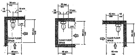
install grab bars at toilets, bathtubs, and showers if it is
known that a dwelling unit is to be occupied by elderly people or people with
severe disabilities.
space required for any fixture unless the toilet or
bathroom is for individual use only, or a clear floor space complying with rule
120-3-20-.4.1 is provided beyond the arc of the door swing within the room.
Fig. 47 Water Closets in Adaptable Bathrooms
(b) Reinforced Areas for Installation of
Grab Bars
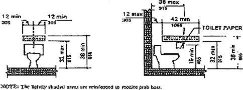
(a) Doors. Doors shall not swing into the clear
floor
Page 125
(2) Water Closets
(a) Clear floor space at the water closet shall be
as shown in Fig. 47(a). The water closet may be located with the clear area at
either side of the water closet.
(b) Water closet height shall be from 15 inches (380
mm) minimum to 19 inches (485 mm) maximum, measured from the floor to the top
of the toilet seat.
(c) Grab bars shall be installed as shown in Fig. 29
and comply with rule 120-3-20-.37, or structural reinforcement or other
provisions shall be made that will allow installation of grab bars in the
locations shown in Fig 47(b).
(d) The toilet paper dispenser shall be installed
within reach in Fig. 47(b).
(3) Lavatory, Mirrors, and Medicine
Cabinets
(a) The lavatory and mirrors shall comply with rule 120-3-20-.30.
(b) If Medicine cabinet is provided under the
lavatory, it shall provide, or shall be removable to provide, the clearances
specified in rule 120-3-20-.30(2).
(c) If a Medicine cabinets are provided above the
lavatory, then the bottom of the medicine cabinet shall
be located with a usable shelf no higher than 44
inches (1120 mm) above the floor.
(4) Bathtubs. If a bathtub is provided, it
shall have the following features:
(a) Floor Space. Clear floor space at bathtubs shall
comply with Fig 33.
Fig. 33
Clear Floor Space at Bathtubs
(a)
With Seat In Tub

(b)
With Seat at Head of Tub
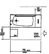
(b) Seat. A removable in-tub seat or permanent seat
at the head end of the tub shall be provided as shown in Fig. 33 and 34. The
structural strength of seats and their attachments shall comply with rule
120-3-20-.34(3). Seats shall be mounted securely and shall not slip during use.
(a) With Seat in Tub
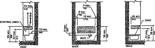
Page 126
Fig. 48 Location of Grab-Bar Reinforcements and
Controls of Adaptable Bathtubs
(b) With Seat at Head of Tub NOTE:
The lightly shaded areas are reinforced to receive grab bars.
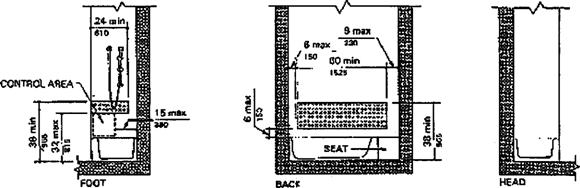
(c) Grab Bars. Grab bars shall be installed within
the range heights shown in Fig. 34 and shall comply with rule 120-3-20-.37, or
structural reinforcement or other provisions, as shown in Fig. 48, shall be
made that will allow installation of grab bars meeting these requirements.
(d) Controls. Faucets arid other controls shall be
located as shown in Fig. 34 and shall comply with rule
120-3-20-.38.
(e) Shower head. A shower spray head shall be
provided with a hose at least 60 inches (1525 mm) long that can be used as a
fixed shower head or as a hand-held shower. If an adjustable height shower head
mounted on a vertical bar is used, the bar shall be installed so as not to
obstruct the use of the grab bars.
(5) Showers.
If
a shower is provided, it shall have the following features:
(a) Size and Clearances. Shower stall size and clear
floor space shall comply with either Fig. 35(a) or (b). The shower stall in
Fig. 35(a) shall be 36 inches by 36 inches (915 mm by 915 mm). The shower stall
in Fig. 35(b) will fit into the same space as a standard bathtub, 60 inches
long.
(b) Seat A seat shall be provided in the shower
stall in Fig. 35(a) as shown in Fig. 36. The seat shall be 17 inches to 19
inches (430 mm to 485 mm) high measured from the bathroom floor and shall be on
the wall opposite the controls. The structural strength of seats and their
attachments shall comply with rule 120-3-20-.34(3). Seats shall be mounted
securely and shall not slip during use.
(c) Grab Bars. Grab bars shall be installed within
the range heights shown in Fig. 37 and shall comply with rule 120-3-20- .37, or
structural reinforcement or other provisions, as shown in Fig. 49, shall be
made that will allow installation of grab bars meeting these requirements.
(d) Controls. Faucets and other controls shall be
located as shown in Fig. 37 and shall comply with rule 120-3-20-.38. In the
shower stall in Fig. 35(a), all controls, faucets, and the shower head shall be
mounted on the side wall opposite the seat.
(e) Shower Head. A shower spray head shall be
provided with a hose at least 60 inches (1525 mm) long that can be used as a
fixed shower head or as a hand-held shower. If an adjustable height shower head
mounted on a vertical bar is used, the bar shall be installed so as not to
obstruct the use of the grab bars.
Page 127
(f) Bathtub and Shower Enclosures.
Enclosures for bathtubs or shower stalls shall not
obstruct controls or transfer form wheelchairs onto shower or bathtub seats.
Enclosures on bathtubs shall not have tracks mounted on their rims.
(g) Clear Floor Space. Clear
floor space at fixtures shall be permitted to overlap.
(5) Kitchens.
Accessible
kitchens and their components shall be on an accessible route and shall comply
with the requirements of 120-3-20-.54.5.
(a) Clearance. Where counters provide the knee
clearances specified in rule 120-3-20-.43(3), clearances between those counters
and all opposing base cabinets, counter tops, appliances, or walls in kitchens
shall be 40 inches (1015 mm) minimum, except in U-shaped kitchens, where such
clearances shall be 60 inches (1525 mm) minimum.
(b) Clear Floor Space. A clear floor space 30 inches
by 48 inches (760 mm by 1220 mm) minimum complying with 4.2.4 that allows
either a forward or a parallel approach by a person in a wheelchair shall be
provided at all appliances in the kitchen, including the range or cook top,
oven, refrigerator/freezer, dishwasher, and trash compactor. Laundry equipment
located in the kitchen shall comply with rule 120-3-20-.54.6.
Fig. 50
Counter Work Surface
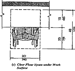
(c) Controls. All controls in kitchens shall comply
with rule 120-3-20-.38.
(a) Before Removal of Cabinets and Base
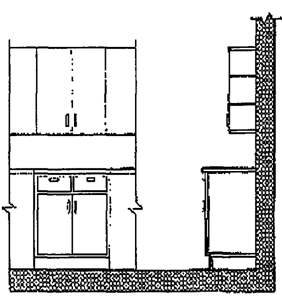
(b) Cabinets and Base Removed and Height
Alternatives
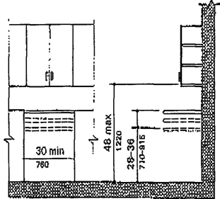
Page 128
(d) Work Surfaces. At least one 30 inches (760 mm)
wide minimum section of counter shall provide a work surface that complies with
the following requirements (See Fig. 50):
(i) The counter
shall be adjustable or replaceable as a unit at variable heights between 28
inches and 36 inches (710 mm and 915 mm), measured from the floor to the top of
the counter surface, or shall be mounted at a fixed height of 34 inches (865
mm) maximum, measured from the floor to the top of the counter surface.
(ii) Base cabinets,
if provided, shall be removable under the full 30 inches (760 mm) minimum
frontage of the counter. The finished floor shall extend under the counter to
the wall.
(iii) Counter thickness and supporting structure
shall be 2 inches (51 mm) maximum over the required clear area.
(iiii) A
clear floor space of 30 inches by 48 inches (760 mm by 1220 mm) minimum shall
allow a forward approach to the counter. The 19 inches maximum of clear floor
space shall be permitted to extend (485 mm)underneath the counter. The knee
space shall have a clear width of 30 inches (760 mm) minimum.
(v) There shall be no sharp or abrasive surfaces
under such counters.
(5) Sink. The sink
and surrounding counter shall comply with the following requirements (See Fig.
51):
(a) The sink and surrounding counter shall be adjustable
or replaceable as a unit at variable heights between 28 inches and 36 inches
(710 mm and 915 mm), measured from the finished floor to the top of the counter
surface or sink rim, or shall be mounted at a fixed height of 34 inches (865
mm) minimum, measured from the finished floor to the top of the counter surface
or sink rim.
(b) Where sinks are installed to be adjustable in
height, rough-in plumbing shall be located to accept connections of supply and
drain
pipes for sinks mounted at the height of 28 inches
(710 mm).
(c) The depth of a sink bowl shall be 6 1/2 inches
(165 mm) maximum. Only one bowl of double-bowl or triple-bowl sinks needs to
meet this requirement.
(d) Faucets shall comply with rule 120-3-20-.38(4).
(1) Before Removal of Cabinets and Base
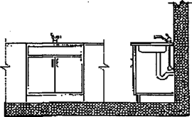
(e) Base cabinets, if provided, shall be removable
under the full 30 inches (760 mm) minimum frontages of the sink and surrounding
counter. The finished flooring shall extend under the counter to the wall.
(f) Counter thickness and supporting structure shall
be 2 inches (50 mm) maximum over the required clear space.
Fig. 51
Kitchen Sink (b)
Cabinets and Base Removed and Height Alternatives
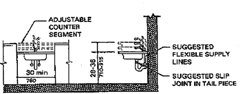
Page 129
Fig. 52
Ovens without Self-Cleaning Feature
(a) Side-Hinged Door
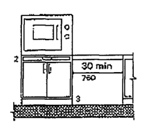
(b) Bottom-Hinged Door
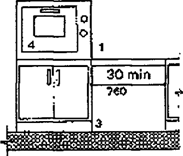
(c) Range Oven
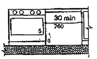
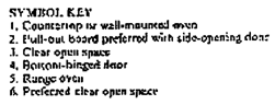
(g) A clear floor space of 30 inches by 48 inches
(760 mm by 1220 mm) minimum shall allow forward approach to the sink. The clear
floor space shall be permitted to extend 19 inches (485 mm) maximum underneath
the sink. The knee space shall have a clear width of 30 inches (760 mm)
minimum.
(h) There shall be no sharp or abrasive surfaces
under sinks. Hot Water supply pipes and drain pipes under sinks shall be
insulated or otherwise covered.
(6) Ranges and Cook tops. Ranges
and Cook tops shall comply with 120-3-20-.54.4.2 and 120-3-20-.54.4.3. If ovens
or Cook tops have knee spaces underneath, they shall be insulated or otherwise
protected on the exposed contact surfaces for protection against bums,
abrasions, or electrical shock. The clear floor space shall be permitted to
overlap the knee space, if provided, by 19 inches (485 mm) maximum. The
location of controls for ranges and Cook tops shall not require reaching across
burners.
Note: Although not required for minimum accessibility,
counter top range units in a counter with adjustable heights are an added
convenience for wheelchair users.
(7) Ovens. Ovens
shall comply with 120-3-20-.54.5.2 and 120-3-20-.54.5.3. Ovens shall be of the self-cleaning
type or be located adjacent to an adjustable height counter with a 30 inches
(760 mm) wide minimum knee space below (See Fig. 52). For side-opening ovens,
the door latch side shall be next to the open counter space, and there shall be
a pull-out shelf under the oven extending the full width of the oven and
pulling out 10 inches (255 mm) minimum when fully extended. Ovens shall have
controls on front panels. Controls shall be permitted to be located on either
side of the door.
Note: Counter top or wall-mounted ovens with side-opening
doors are easier for people in wheelchairs to use. Clear spaces 30 inches {760
mm) wide minimum under counters at the side of ovens are an added convenience.
The pull-out board or fixed shelf under side-opening oven doors provides a
resting place for heavy items being moved from the oven to a counter.
Page 130
(8) Refrigerator/Freezers. Refrigerators
and freezers shall comply with 120-3-20-.54.5.3. Provisions shall be made for
refrigerator / freezers that are:
(a) Of the Vertical Side-by-side combination freezer
and refrigerator type; or
(b) Of the over-and-under type and meet the
following requirements:
(i) appliances shall have at least 50 percent of the
freezer space and at least 50 percent of the refrigerator space located 54
inches (1370 mm) maximum above the floor.
(ii) Other combination refrigerators and freezers
shall have at least 50 percent of the freezer space and 100 percent of the
refrigerator space and controls 54 inches (1370 mm) maximum above the floor.
Freezers with less than 100 percent of the storage volume within the limits
specified in rule 120-3-20-.13(5) or rule 120-3-20-.13(6) shall be the
self-defrosting type.
Note: Side-by-side refrigerator/freezers provide the most
usable freezer compartments. Locating refrigerators so that their doors swing
back 180 degrees is more convenient for wheelchair users.
(?) Dishwashers. Dishwashers
shall comply with 120-3-20-.54.5.2 and
120-3-20-.54.5.3. Dishwashers shall
have all rack space accessible from the
front of the machine for loading and
unloading dishes.
(10) Kitchen Storage. Cabinets,
drawers, and self storage areas shall comply with rule 120-3-20-.36 and shall
have the following features:
(a) Maximum height shall be 48 inches (1220 mm) for
at least one shelf of all cabinets and storage shelves mounted above work
counters (See Fig. 50).
(b) Door pulls or handles for wall cabinets shall be
mounted as close to the bottom of cabinet doors as possible. Door pulls or
handles for base cabinets shall be mounted as close to the top of cabinet doors
as possible.
Note: Full-height cabinets or tall cabinets are
recommended to be provided rather than cabinets mounted over work counters.
Additional storage space located conveniently adjacent to kitchens makes up for
space lost when cabinets under counters are removed.
(6) Laundry Facilities. If
laundry equipment is provided within individual accessible dwelling units, or
if separate laundry facilities serve one or more accessible dwelling units,
they shall meet the requirements of 120-3-20-.54.6.1 and 120-3-20-.54.6.2.
(a) Location. Laundry Facilities and laundry
equipment shall be on an accessible route..
(b) Washing Machines
and Clothes Dryers. Accessible washing machines and clothes dryers in
common-use laundry rooms shall be front loading and shall comply with
120-3-20-.13(4).
(c) Controls. Laundry equipment shall comply with
120-3-20-.38.
Fig. 37 Grab Bars at Shower Stalls
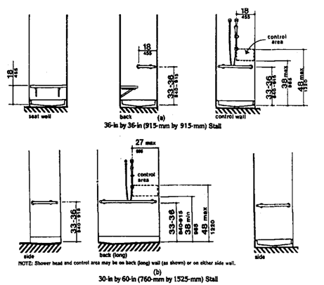
Page 131
TABLE 4
|
Accessible spaces
|
Section
|
Application
|
|
1. Space allowances
|
4.2
|
All rooms and spaces
|
|
2. Accessible routes
|
4.3
|
(a) Within dwelling units to all rooms and spaces
(b) Connecting accessible dwelling unit(s) to
accessible entrance(s) and to common-use spaces and facilities.
(c) From public transportation stops, accessible
parking spaces, accessible passenger loading zones and public streets, or
sidewalks to accessible entrance(s)
(d) Connecting accessible buildings, facilities,
elements, and spaces that are on the same site.
(e) Connecting accessible buildings or facility
entrances with accessible spaces and elements within the building or
facility.
|
|
3. Floor surfaces
|
4.5
|
Accessible routes, rooms and spaces.
|
|
4. Parking and passenger Loading zones
|
4.6
|
If provided at facility.
|
|
5. Windows
|
4.12
|
If operable windows are provided within dwelling
units
|
|
6. Doors
|
4.13
|
At entrance; to and in accessible spaces.
|
|
7. Entrances
|
4.14
|
To dwelling unit
|
|
8. Storage
|
4.23
|
If provided within in accessible spaces.
|
|
9. Controls
|
4.25
|
Within dwelling units, including heating,
ventilating, and air conditioning equipment (other than air distribution
registers) requiring regular, periodic maintenance and adjustment by the
occupant of the dwelling unit
|
|
10. Emergency alarms
|
426
|
If provided within the dwelling unit
|
|
11. Bathrooms
|
120-3-20-.54.4
|
Design for fixed installation of grab bars within
specified range of heights, or with provision for subsequent addition of grab
bars within the range.
|
|
12. Kitchens
|
120-3-20-.54.5
|
Work surfaces and sinks may be designed for fixed
installation within specified range of heights, or for adjustable heights
within the range.
|
|
13. Laundry facilities
|
120-3-20-.54.6
|
If provided in dwelling unit or if common-use
facilities serving accessible dwelling unit.
|
|
14. Common-use spaces and facilities
|
4.2 through
120-3-20-.54
|
If provided at facility and serving accessible
dwelling unit.
|
|
15. Patios, terraces, balconies, carports, and
garages.
|
4.2 through 120-3-20-~54
|
If provided with accessible dwelling unit.
|
Page 132
Georgia State Resources
American
Foundation for the Blind 100 Peachtree Street, NW Atlanta, GA 30303
404-525-2303
Department
of Natural Resources Historic Preservation Division 500 Healy Building 57
Forsyth Street, NW Atlanta, GA 30303 404-656-2840 404-651-8739 (Fax) Mr. Mark
R. Edwards
Disability
Action Center (DAC) 246 Sycamore St. Suite 100 Decatur, GA 30030
404-687-8890(V/TDD)
Division
of Rehabilitation Services ADA Coordinator 2 Peachtree St, NE Atlanta, GA 30303
404-657-3050
Georgia
ADA Exchange, Inc. 2230 Seaman Circle Chamblee, GA 30341 770-451-2340
Georgia
Relay Service 800-255-0056 (TDD) 800-255-0135 (Voice)
Georgia
State Fire Marshal's Office Office of the Commissioner of Insurance Suite 620,
West Tower, Floyd Building 2 Martin Luther King, Jr. Drive Atlanta, GA 30334
404-656-9754 404-656-4031 (TDD) 404-657-7009 (Fax) Mr.
Vic Rachael
Governor's
Council on Developmental Disabilities Suite 210, Third Floor 2 Peachtree St.,
NW Atlanta, GA 30303 404-657-2126 404-657-2133 (TDD) 888-275-4233 Ms. Marcey L.
Dolgoff
State ADA
Coordinator
Georgia
Building Authority
1 Martin
Luther King Jr. Drive
Suite
1554, East Tower, Floyd Building
Atlanta,
GA 30334
404-657-7313
404-657-9993
(TDD)
404-657-1741
(Fax)
Ms. Linda
Priest
TechKnowledge
490 Tenth Street Atlanta, GA 30356 800-726-9119
Federal Government Resources
Architectural
and Transportation Barriers Compliance Board (ATBCB or Access Board) 1331 F
Street, NW, Suite 1000 Washington, DC 20004-1111 800-USA-ABLE (V) 800-993-2833
(TDD) 202-272-5434(V) 202-272-5449 (TDD)
Department
of Justice (DOJ) Civil Rights Division Disability Rights Section P.O. Box 66738
Washington, DC 20035-9996 800-514-0301 (V)
December 11,
1987